Coil component

a technology of components and coils, applied in the direction of transformers/inductances, magnetic cores, solid-state diffusion coatings, etc., can solve the problems of reducing the volume ratio of fe—cr, the inductance of the component itself will drop, and the saturated magnetic flux density of the material cannot be utilized to increase etc., to achieve the effect of increasing the saturated magnetic flux density of the component itself and high volume resistivity

Active Publication Date: 2012-07-26
TAIYO YUDEN KK
View PDF4 Cites 47 Cited by
  • Summary
  • Abstract
  • Description
  • Claims
  • Application Information

AI Technical Summary

Benefits of technology

[0015]According to the present invention, magnetic alloy grains constituting the magnetic body have an oxide film (=insulation film) of magnetic alloy grains on their surface, and magnetic alloy grains in the magnetic body directly bind with one another via the oxide film that serves as an insulation film, and also magnetic alloy grains near the coil adhere to the coil via the oxide film that serves as an insulation film, and for these reasons a high volume resistivity of the magnetic body mainly constituted by magnetic alloy grains can be ensured. In addition, when the magnetic body does not contain a glass component, the volume ratio of magnetic alloy grains does not drop, unlike when there is a glass component in the magnetic body, which prevents the saturated magnetic flux density of the component itself from dropping due to a lower volume ratio.
[0016]In other words, although the coil component is of the type where the coil is directly contacting the magnetic body, the saturated magnetic flux density of the component itself can be increased by effectively utilizing the saturated magnetic flux density of the magnetic alloy material, which helps meet the demand for electrical current amplification and also prevents the phenomenon of current leaking from the coil to the magnetic body and disturbing the magnetic field, which in turn prevents the inductance of the component itself from dropping.

Problems solved by technology

In essence, without ensuring a high volume resistivity of the magnetic body itself which is constituted by Fe—Cr—Si alloy grains, the saturated magnetic flux density of the material cannot be utilized to increase the saturated magnetic flux density of the component and, due to the phenomenon of current leaking from the coil to the magnetic body and disturbing the magnetic field, the inductance of the component itself will drop.
However, this manufacturing method allows the glass component in the magnetic paste to remain in the magnetic body, and this glass component in the magnetic body reduces the volume ratio of Fe—Cr—Si alloy grains, which in turn lowers the saturated magnetic flux density of the component itself.

Method used


Image

  • Coil component
  • Coil component
  • Coil component

Examples


Embodiment Construction

[0045]The coil component proposed by the present invention has a magnetic body and a coil formed on this magnetic body. Examples of such coil component include a coil component of the laminated type (laminated inductor, etc.) and coil component comprising a conductive wire wound around a magnetic body serving as the magnetic core. The following explains the characteristics of the present invention by explaining a typical coil component.

[0046][Example of Specific Structure of Coil Component of Laminated Type]

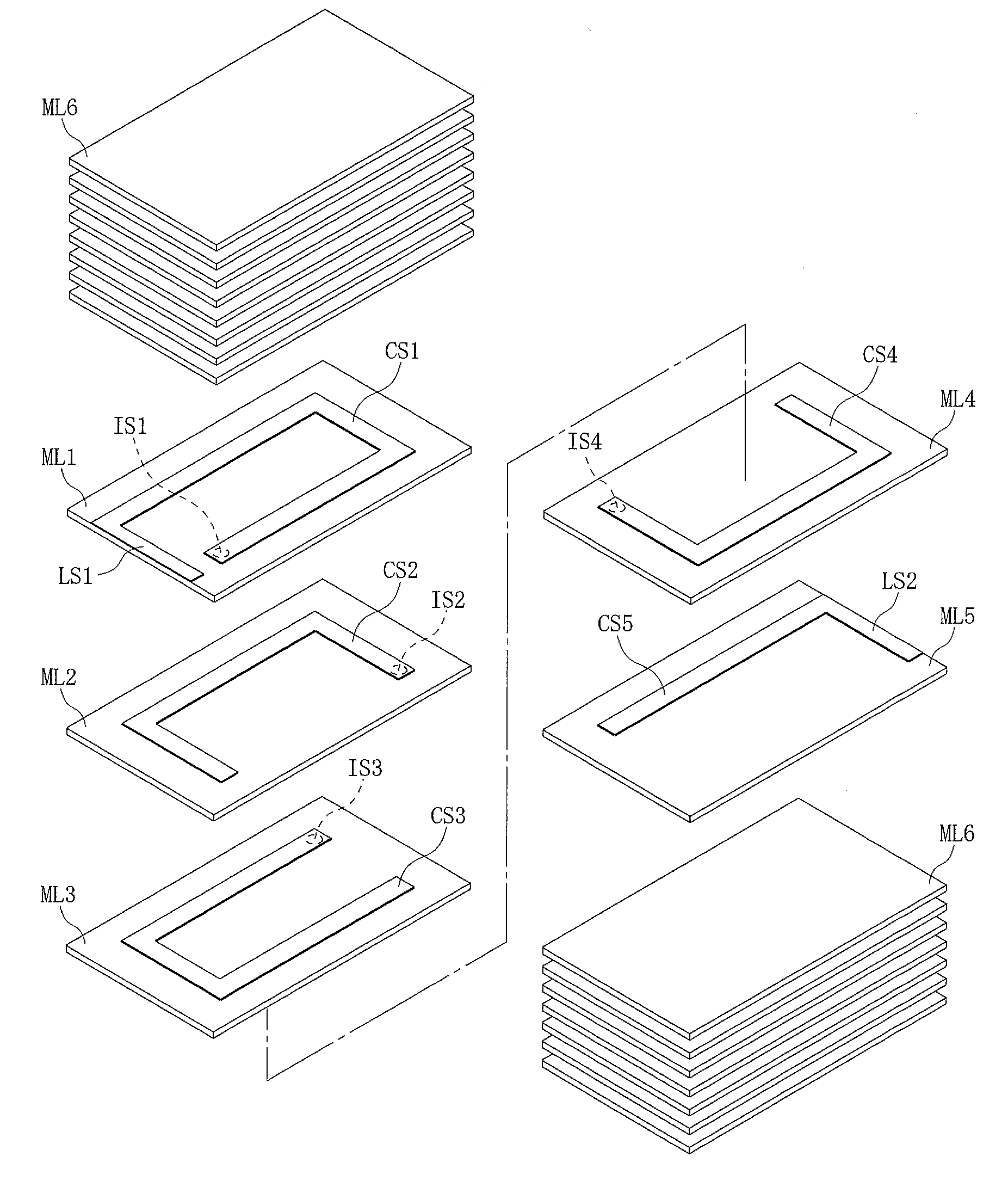
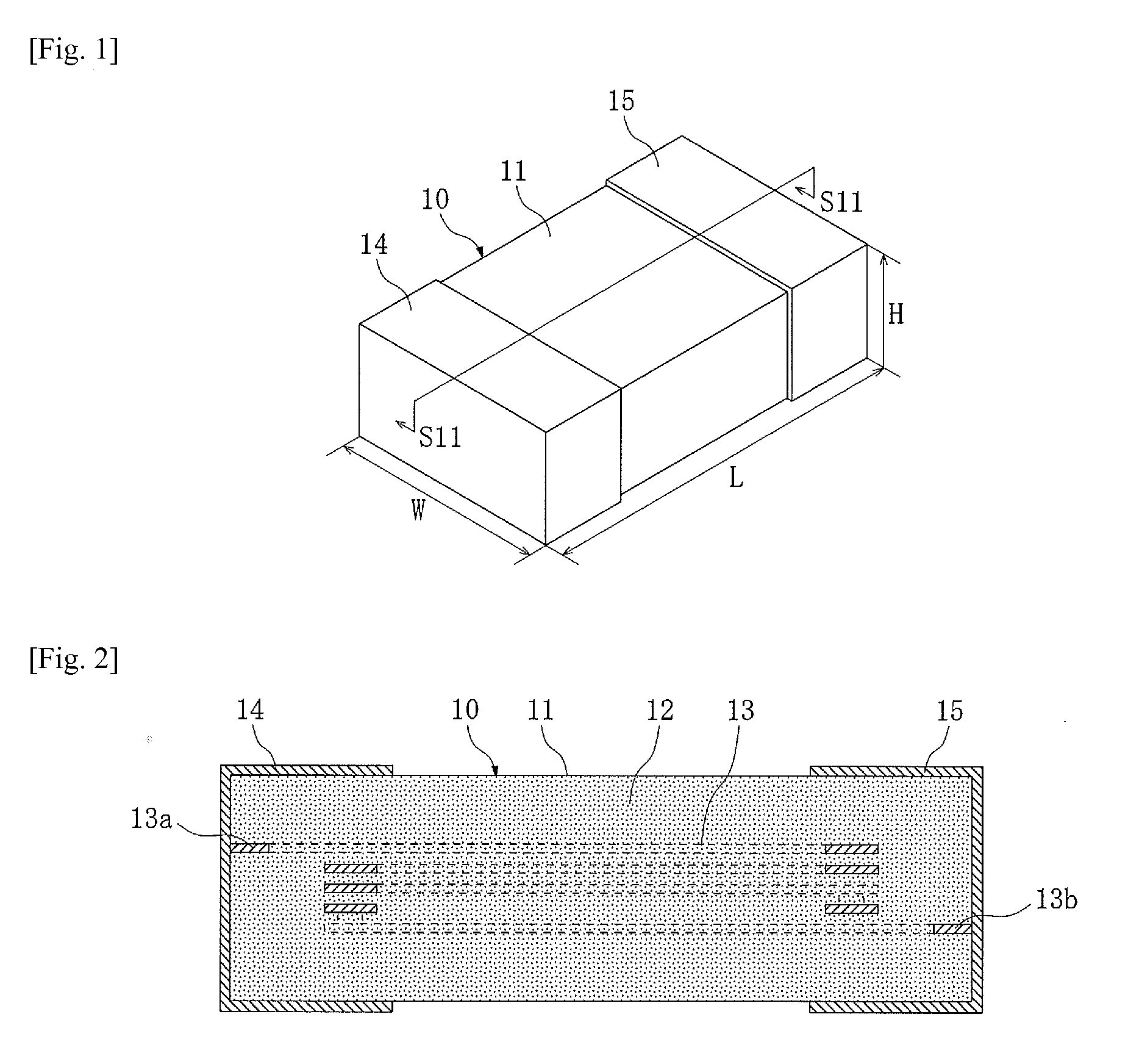
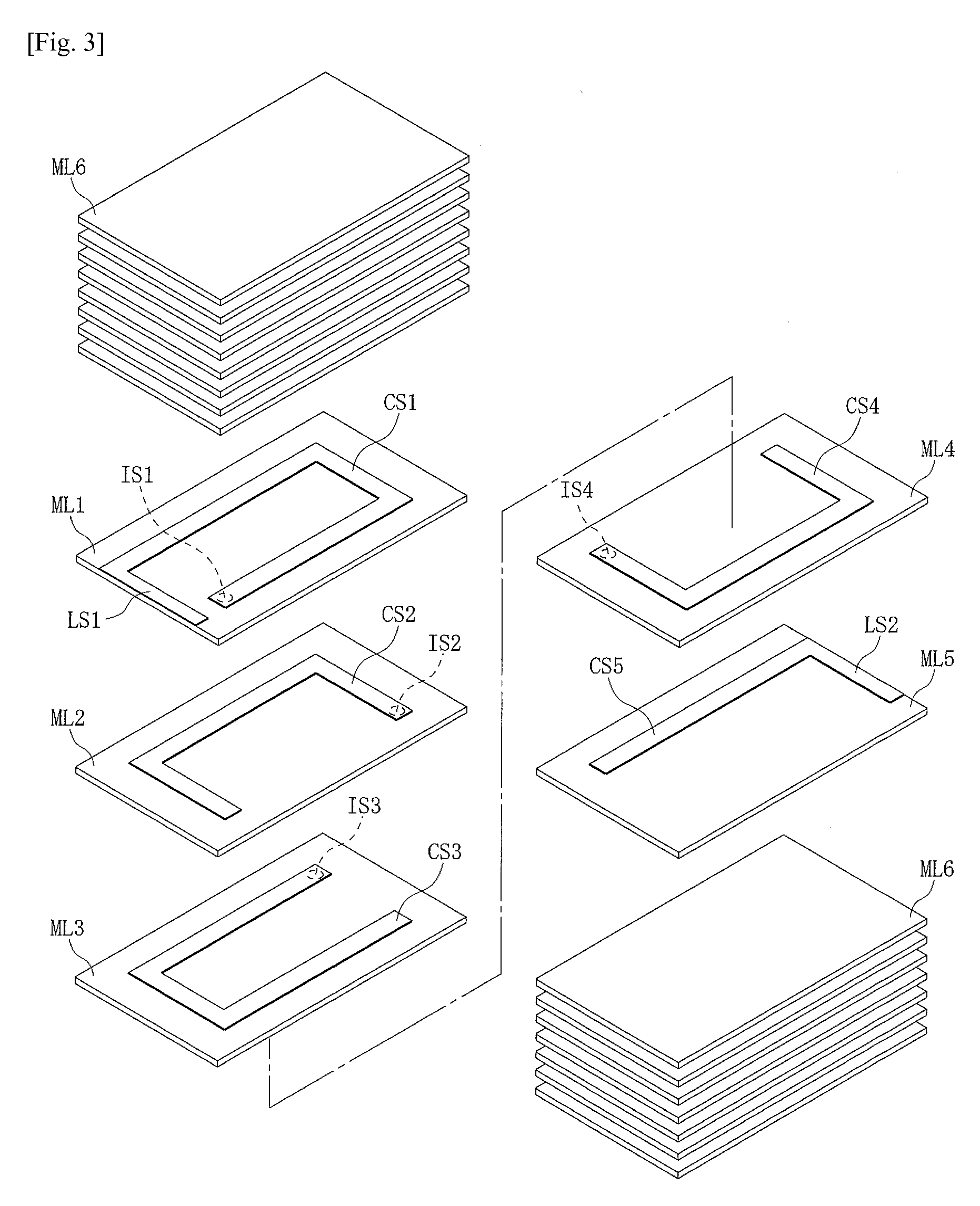
[0047]First, an example of specific structure where the present invention is applied to a coil component of the laminated type is explained by referring to FIGS. 1 to 5.

[0048]A coil component 10 shown in FIG. 1 has a rectangular solid shape of approx. 3.2 mm in length L, approx. 1.6 mm in width W, and approx. 0.8 mm in height H. This coil component 10 has a main component body 11 of rectangular solid shape and a pair of external terminals 14, 15 provided at both ends in the lengt...


PUM

PropertyMeasurementUnit
grain sizeaaaaaaaaaa
heightaaaaaaaaaa
grain sizeaaaaaaaaaa

Abstract

A coil component is of the type where a helical coil is directly contacting a magnetic body, which is still capable of meeting the demand for electrical current amplification. A coil component, comprising a magnetic body mainly constituted by magnetic alloy grains, and a coil formed on the magnetic body; wherein an oxide film of the magnetic alloy grains is present on the surface of each of the magnetic alloy grains, and based on grain size by volume standard, the magnetic alloy grains have a d50 in a range of 3.0 to 20.0 μm, d10 / d50 in a range of 0.1 to 0.7, and d90 / d50 in a range of 1.4 to 5.0.

Description

BACKGROUND[0001]1. Field of the Invention[0002]The present invention relates to a coil component structured in such a way, among others, that a helical coil is covered with a magnetic body.[0003]2. Description of the Related Art[0004]Coil components (so-called “inductance components”), representative examples of which are inductors, choke coils and transformers, are structured in such a way that a helical coil is covered with a magnetic body, an insulating covering conductive wire is wound around a magnetic body, or the like. For the magnetic body covering the coil, Ni—Cu—Zn ferrite and other ferrites (=ceramics whose main constituent is iron oxide) are generally used.[0005]In recent years, there has been a demand for coil components of this type offering electrical current amplification (=higher rated current) and, to meet this need, switching the material for the magnetic body from conventional ferrites to Fe—Cr—Si alloy is being examined (refer to patent Literature 1).[0006]This ...

Claims


Application Information

Patent Timeline
Patent Type & Authority Applications(United States)
IPC IPC(8): H01F27/24B22F3/10B22F1/02B22F1/16
CPCB22F1/02H01F1/24B22F3/24C22C1/02C22C33/02H01F1/14766B22F2998/10C23C8/10H01F27/255H01F1/33C22C5/06H01F41/0246B22F3/16B22F9/08B22F1/16
Inventor MATSUURA, HITOSHIKOBAYASHI, TOMOMIOKINO, YOSHIKAZUIWAO, HIDEMINOGI, KENICHIROOTAKE, KENJI
Owner TAIYO YUDEN KK
Why Eureka
Try Eureka