
Syncronizing wireless devices

a wireless device and wireless technology, applied in the direction of synchronisation arrangement, network traffic/resource management, electrical equipment, etc., can solve the problem of reducing the efficiency of network communication protocol in terms of available bandwidth, and achieve the effect of reducing the efficiency of network communication protocol and sufficient frame density

Active Publication Date: 2012-07-26
NXP BV
View PDF8 Cites 31 Cited by
  • Summary
  • Abstract
  • Description
  • Claims
  • Application Information

AI Technical Summary

Benefits of technology

[0010]Proposed is the implementation of a synchronization channel for a wireless network which complements other wireless frames (e.g. beacon frames, data frames) that can be used for synchronisation purposes. The synchronization channel may enable the transmission of dedicated synchronisation (sync) frames whenever required. The synchronisation channel may only be employed when the density of the other wireless frames is too low for keeping the network devices synchronised. Such transmission of sync frames may ensure sufficient frame density to enable receiving devices to get and stay synchronized.
[0011]The proposed approach may exclude the use of more frequent (permanent) beacons which reduce the network communication protocol efficiency in terms of available bandwidth. It may also exclude the use of synchronisation frames when the density of other wireless frames that can be used for synchronisation is sufficiently high.
[0013]Embodiments may also allow the use of a RC oscillator which reduces the power consumption and helps the miniaturization.

Problems solved by technology

The proposed approach may exclude the use of more frequent (permanent) beacons which reduce the network communication protocol efficiency in terms of available bandwidth.

Method used


Image

  • Syncronizing wireless devices
  • Syncronizing wireless devices
  • Syncronizing wireless devices

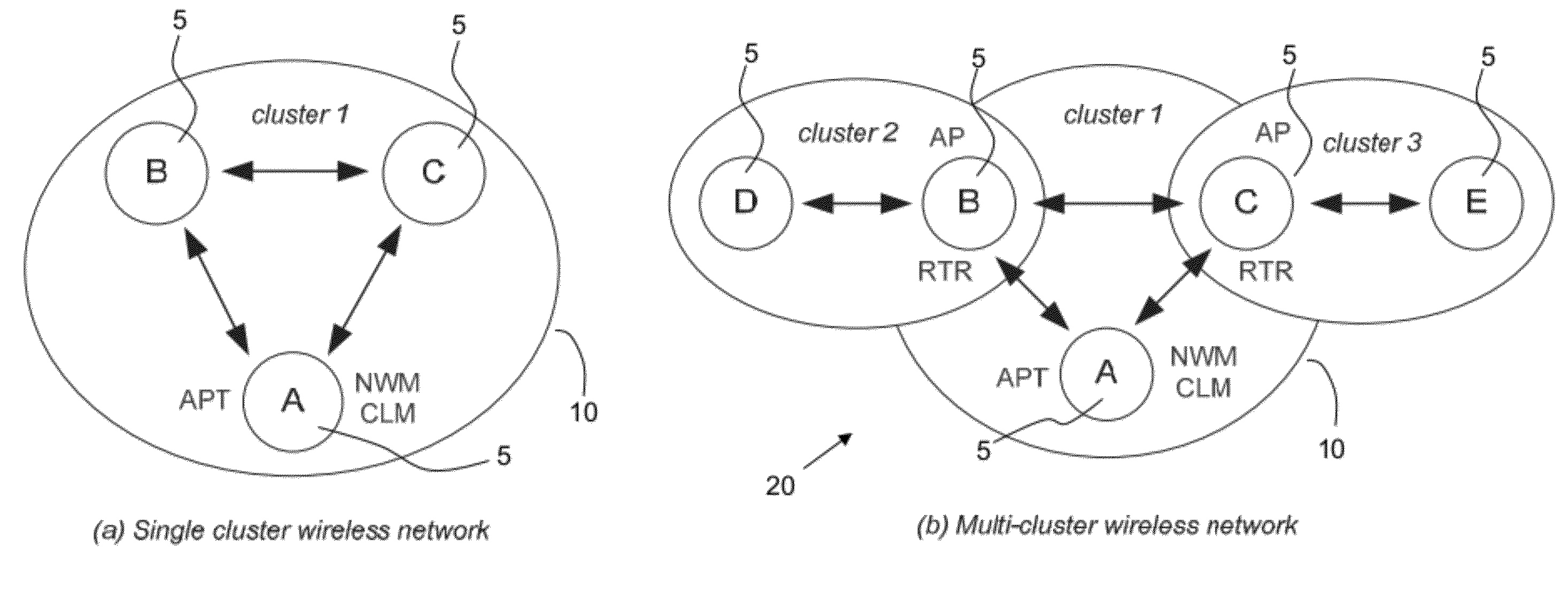
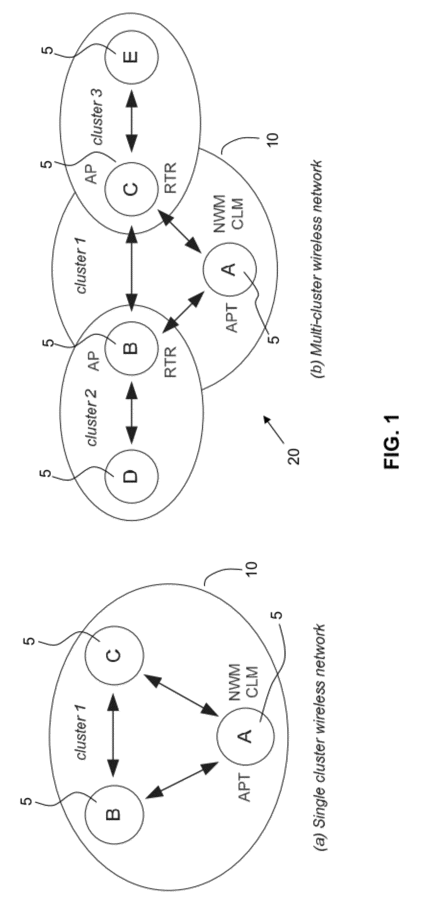
Examples


Embodiment Construction

[0026]The same reference numbers have been used in different figures to denote the same components and layers, and the description is not repeated.

[0027]Embodiments of the invention will be described in the context of a proposed network protocol intended for use with a family of wireless hearing aid devices. Compared to a conventional network protocol for wireless hearing aid devices, the proposed embodiments may provide improved flexibility for setting up connections. Embodiments may also operate with different types of physical layer and in multi-cluster wireless networks.

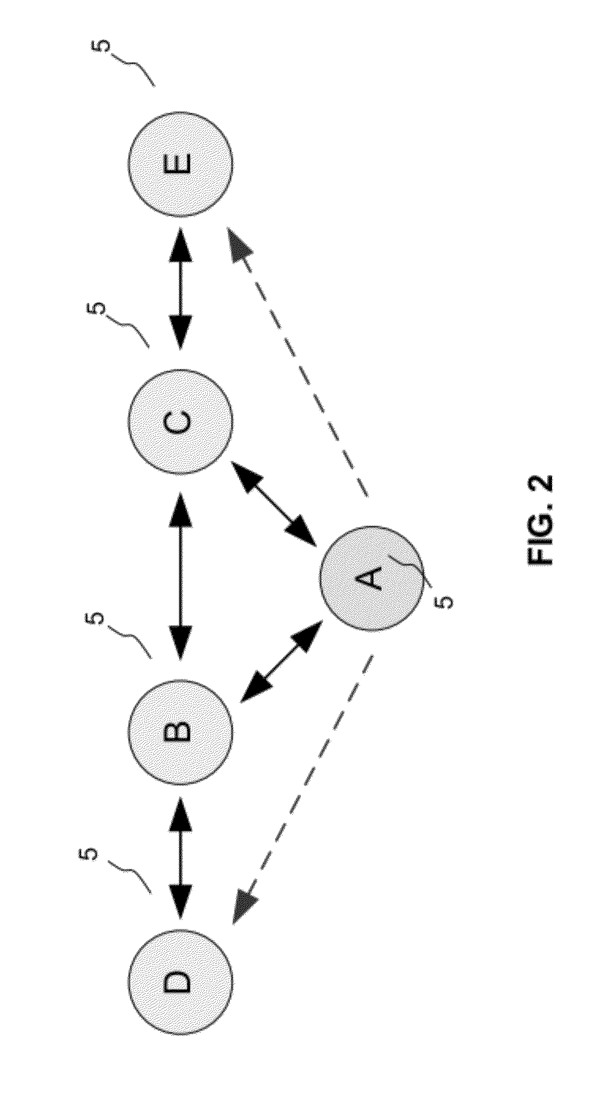
[0028]A network based on the proposed network protocol is organized as a mesh network with distributed intelligence and distributed responsibilities. Mesh networking is a method to route data between nodes. It allows creating connections between devices that are not within each others range by “hopping” from node to node until the destination is reached. It also allows reconfiguring connections around broken or b...


PUM


Abstract

A method of synchronising the reference clock of a first wireless device with a master reference clock of a second wireless device via a wireless network. The method involves transmitting, from the second wireless device to the first wireless device, a dedicated synchronisation frame via a dedicated synchronisation channel; receiving the dedicated synchronisation frame at the first wireless device; and synchronising the reference clock of the first wireless device with the master reference clock of the second wireless device based on the received dedicated synchronisation frame.

Description

[0001]This application claims the priority under 35 U.S.C. §119 of European patent application no. 11152178.7, filed on Jan. 26, 2011, the contents of which are incorporated by reference herein.FIELD OF THE INVENTION[0002]This invention relates to synchronizing wireless devices, and more particularly to synchronizing wireless devices in a wireless network.BACKGROUND OF THE INVENTION[0003]Wireless network devices typically need to be synchronized with each other in order to avoid a large timing offset which can impact the correct reception of wireless data. Accordingly, it is known to derive the timing for the network communication protocol from a local master clock.[0004]In a wireless network device, e.g. magnetic induction (MI)-based, the local master clock can be the RC oscillator of the (MI) physical layer, the master clock of an audio interface or an external crystal oscillator. An on-chip local oscillator of the device's protocol processor is then locked to this master clock, a...

Claims


Application Information

Patent Timeline
IPC IPC(8): H04W56/00
CPCH04W28/06H04W56/001H04R2420/07H04W92/18H04W56/0035
Inventor PHILIPS, NORBERTCLAESSENS, VALENTINTHOEN, STEVEN MARKWALRANT, THIERRY G C
Owner NXP BV
Learn More