Ejector apparatus for fuel cell

a fuel cell and ejector technology, applied in mechanical apparatus, machines/engines, electrochemical generators, etc., can solve problems such as displacement toward the opening side, and achieve the effects of increasing the face pressure of the seat face, and reducing the diameter of the seat portion

Inactive Publication Date: 2012-07-26
KEIHIN CORP +1
View PDF2 Cites 16 Cited by
  • Summary
  • Abstract
  • Description
  • Claims
  • Application Information

AI Technical Summary

Benefits of technology

[0008]The present invention is achieved in view of the above mentioned point and provides an ejector apparatus for a fuel cell that can prevent a nozzle on a movable side from being displaced toward an opening side with respect to a needle on a fixed side when supply pressure of a fuel gas is applied to an ejector main body.
[0013]As a result thereof, according to the ejector apparatus of the invention, even when the supply pressure of the fuel gas supplied into the first chamber is applied thereto, it is possible to suitably prevent the nozzle on a movable side from being displaced toward the opening side with respect to the needle on a fixed side.
[0014]Furthermore, according to the ejector apparatus of the invention, because the displacement of the nozzle toward the opening side is prevented and the predetermined position of the nozzle is held, it is possible to prevent discharge pressure of the fuel gas discharged from the nozzle from being excessive. Furthermore, because the nozzle is held at the predetermined position, it is possible to perform a nozzle control from the predetermined position; therefore, it is possible to widen a control width (increase a controllable range) of the discharge pressure of the fuel gas discharged from the nozzle and enhance a control stability of the nozzle.
[0016]According to the ejector apparatus of the invention, the seat portion is provided at the bearing member arranged in the nozzle, and thereby it is possible to obtain the seat portion reduced in diameter compared to a case of the seat portion being provided on an end face of the nozzle. Furthermore, by reducing the diameter of the seat portion, it is possible to increase face pressure of the seat face and enhance a seat close contact of the seat portion in comparison with that of a conventional seat portion.

Problems solved by technology

Incidentally, according to the ejector disclosed in the Japanese Patent Laid-Open Publication No. 2009-144557, there is a problem that when the supply pressure of the hydrogen gas supplied to the first fluid chamber is applied, the nozzle results in being displaced toward an opening side.

Method used


Image

  • Ejector apparatus for fuel cell
  • Ejector apparatus for fuel cell
  • Ejector apparatus for fuel cell

Examples


Embodiment Construction

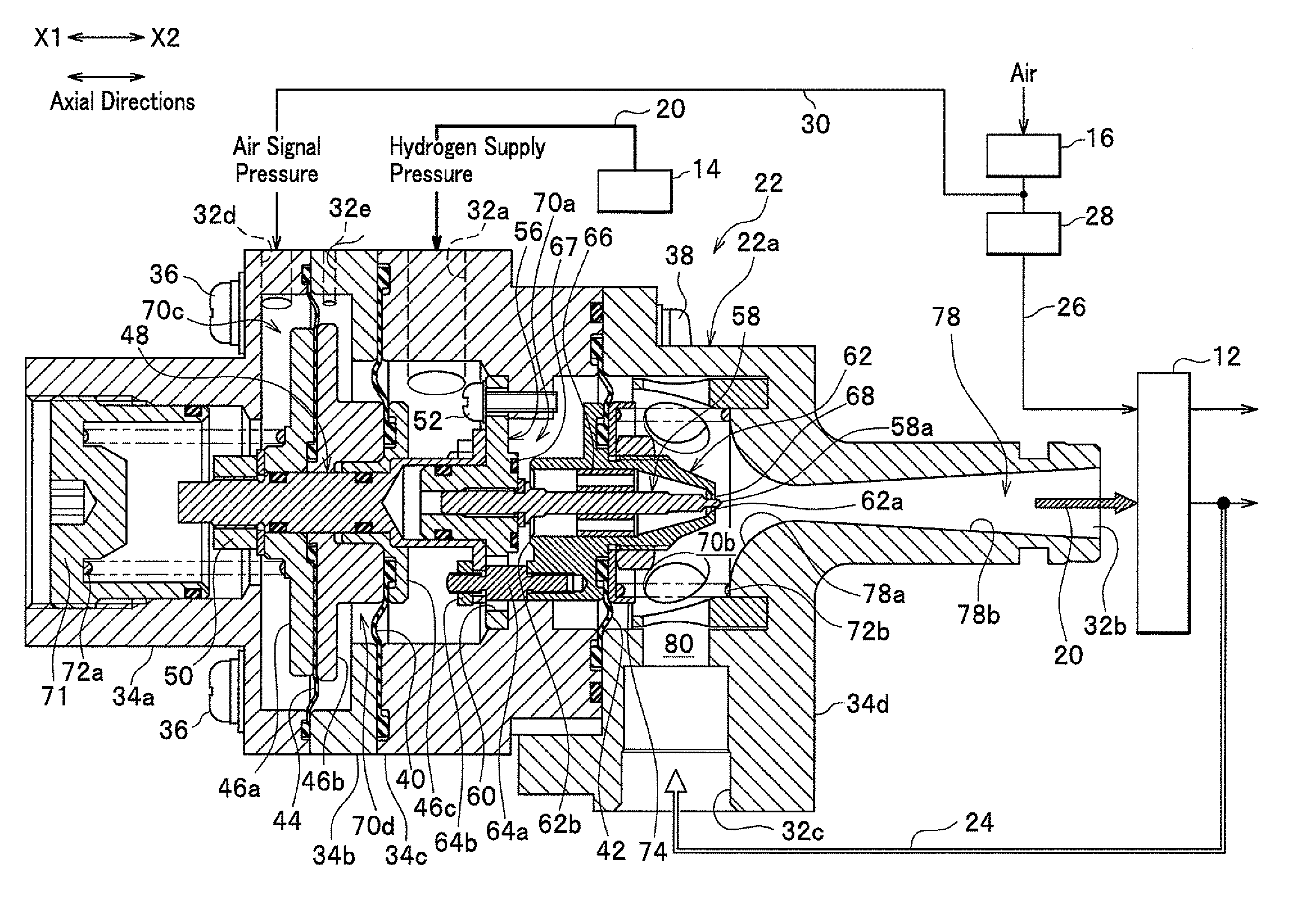
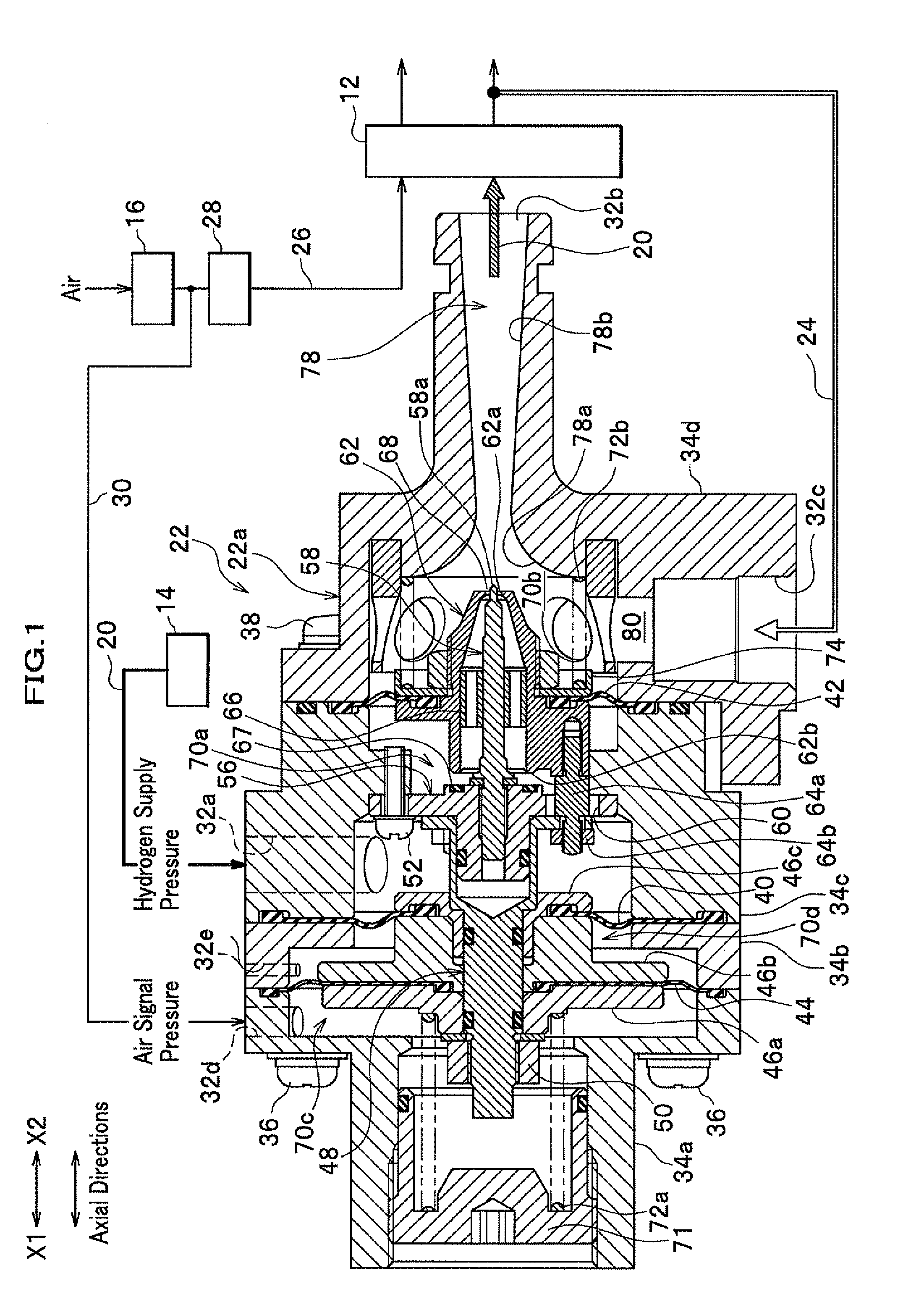
[0021]Next will be described an ejector apparatus for a fuel cell (hereinafter simply referred to as “ejector apparatus” or “ejector” as needed) of embodiments of the present invention in detail with reference to drawings as needed after describing a fuel cell system where the ejector apparatus is incorporated.

[0022]As shown in FIG. 1, the fuel cell system comprises: a fuel cell 12; a hydrogen tank 14, in which a high-pressure hydrogen gas is filled, configured to supply the hydrogen gas to the fuel cell 12 as a fuel gas; an air compressor 16 configured to supply compressed air containing an oxidizer gas (oxygen gas) to the fuel cell 12; and a gas-liquid separation and dilution unit (not shown) for separating a non-reacted hydrogen gas exhausted from the fuel cell 12 into a gas (hydrogen gas) and a liquid (water), and diluting the separated hydrogen gas by non-reacted air exhausted from the fuel cell 12.

[0023]The fuel cell 12 comprises, for example, a polymer electrolyte fuel cell (...


PUM

PropertyMeasurementUnit
areaaaaaaaaaaa
pressureaaaaaaaaaa
power-generation efficiencyaaaaaaaaaa

Abstract

An ejector apparatus for a fuel cell includes an ejector main body including an inlet port, an outlet port, a suction port, and an oxidizer-gas supply port, a first to third chambers provided in the body, a nozzle having a nozzle hole discharging the fuel gas, a diffuser mixing the fuel gas discharged from the nozzle hole and the fuel offgas exhausted from the fuel cell and returned to the suction port, a needle fixed on a side of the body and extending along an axial direction of the nozzle in a hollow portion thereof, and first and second diaphragms arranged to oppose each other, and changing an opening area in a gap between the nozzle hole and an outer peripheral face of a top end of the needle, wherein a pressure receiving area of the first diaphragm is set to be larger than that of the second diaphragm.

Description

BACKGROUND OF THE INVENTION[0001]1. Field of the Invention[0002]The present invention relates to an ejector apparatus for a fuel cell which the apparatus is incorporated in a fuel cell system and mixes a fuel offgas, which is exhausted from the fuel cell, with a fuel gas newly supplied and recirculates the fuel offgas.[0003]2. Description of the Related Art[0004]For example, in a fuel cell system, in order to enhance a power-generation efficiency of a fuel cell, it is used an ejector that mixes a fuel offgas (hydrogen offgas), which is exhausted from the fuel cell, with a fuel gas (hydrogen gas) newly supplied and recirculates the fuel offgas.[0005]Regarding this kind of ejector, for example, according to Japanese Patent Laid-Open Publication No. 2009-144557, it is disclosed an ejector that comprises a first fluid chamber where a hydrogen gas is supplied, a bar-like needle, a nozzle for discharging the hydrogen gas supplied to the first fluid chamber from a discharge port (nozzle ho...

Claims


Application Information

Patent Timeline
Patent Type & Authority Applications(United States)
IPC IPC(8): H01M8/06
CPCH01M8/04097Y02E60/50H01M8/04201F04F5/16F04F5/46H01M8/04104H01M8/04089H01M8/04082
Inventor KATO, TAKAHIDEIKENAGA, TAKAOFUKUMA, KAZUNORI
Owner KEIHIN CORP
Why Eureka
Try Eureka