Polishing method and polishing apparatus

a technology of polishing apparatus and surface, which is applied in the direction of grinding machine components, manufacturing tools, lapping machines, etc., can solve the problems of insufficient polishing rate of surface (to be polished) of substrate, unpolished copper film may remain in scattered state, and the surface to be polished is not easy to achieve sufficient polishing rate. , to achieve the effect of sufficient polishing ra

Inactive Publication Date: 2012-07-26
EBARA CORP
View PDF10 Cites 24 Cited by
  • Summary
  • Abstract
  • Description
  • Claims
  • Application Information

AI Technical Summary

Benefits of technology

[0025]The present invention makes it possible to polish a surface (surface to be polished) of a substrate at a sufficient polishing rate and obtain a desired polishing profile while preventing an unpolished portion from remaining on the surface of the substrate after polishing.

Problems solved by technology

However, it has been generally difficult to carry out polishing of a surface (surface to be polished) of a substrate at a sufficient polishing rate and to obtain a desired polishing profile without leaving an unpolished portion on the surface of the substrate after polishing.
For example, when a copper film formed on a surface of a substrate is polished while controlling the temperature of a polishing pad at a constant temperature in order to obtain a sufficient polishing rate, the copper film will not be completely polished away.
Thus, a considerable amount of unpolished copper film may remain in a scattered state on the surface of the substrate after polishing.

Method used


Image

  • Polishing method and polishing apparatus
  • Polishing method and polishing apparatus
  • Polishing method and polishing apparatus

Examples


case 1

[Case 1]

[0054]A substrate W is prepared which, as shown in FIG. 8, has insulating films 902, 903 having via holes 904 and trenches 905, a barrier film 906 formed on the insulating films 902, 903, and a metal film 907 formed on the barrier film 906. Those portions of the metal film 907, which are embedded in the via holes 904 and the trenches 905, constitute metal interconnects. In the case 1, the metal film is a copper film and the metal interconnects are copper interconnects.

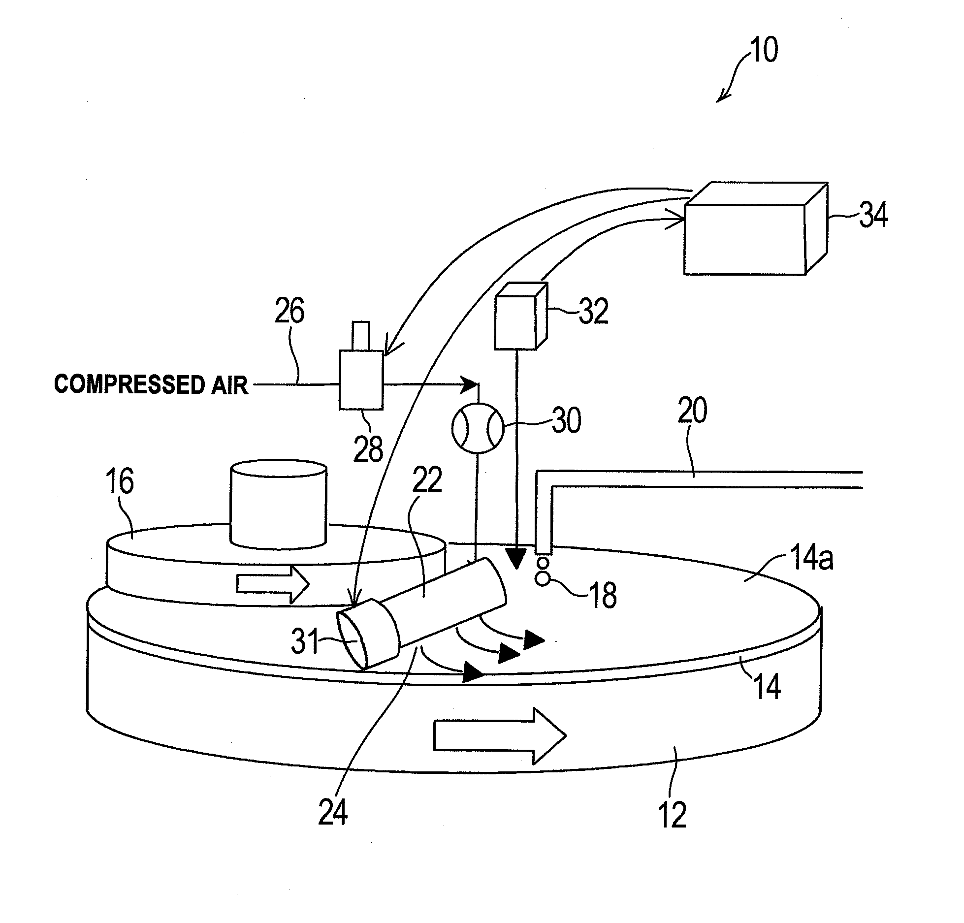
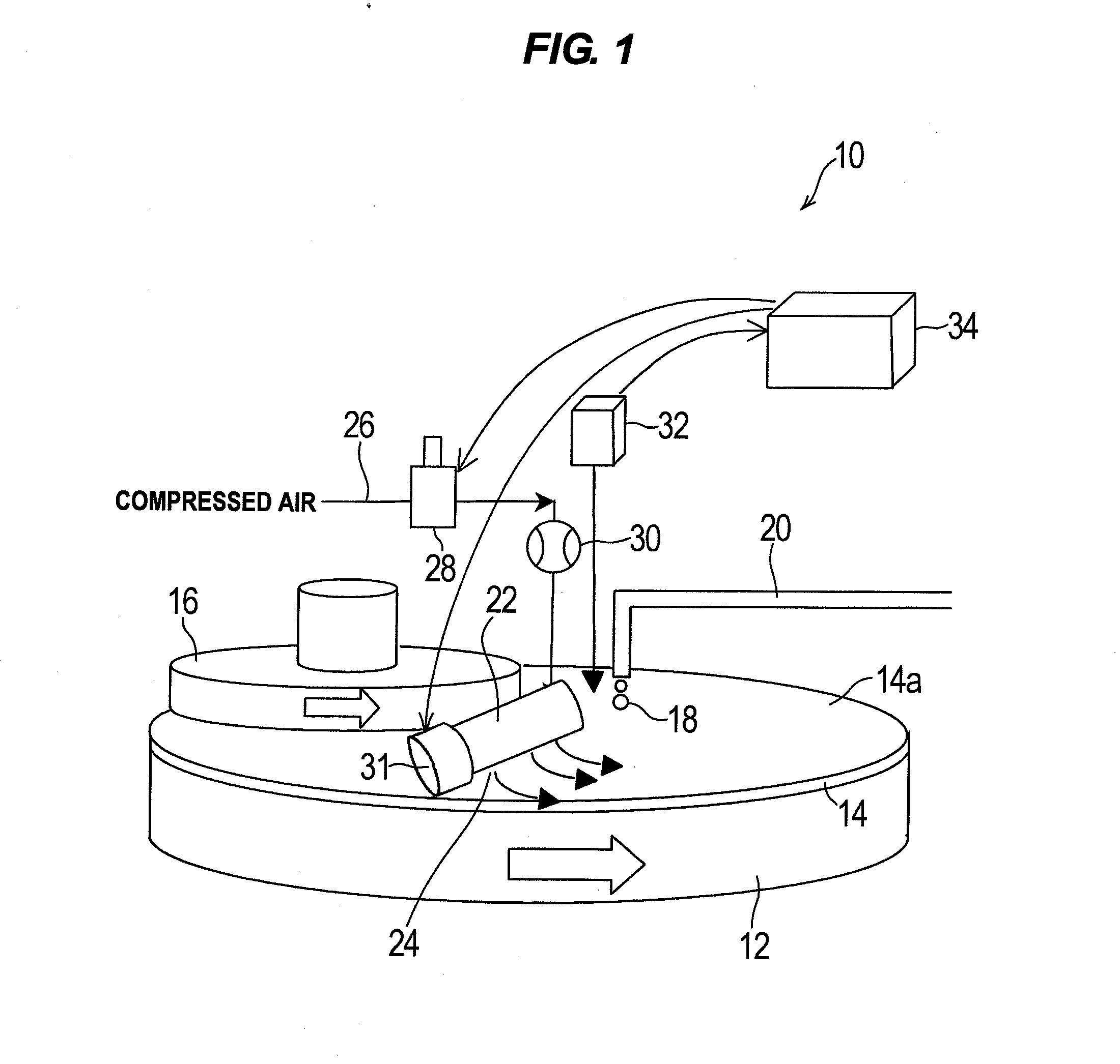
[0055]First, the supply pressure of compressed air to be supplied to the cooling nozzles 24 is confirmed. If this supply pressure is less than a specified pressure, a warning is issued and processing of subsequent substrates is stopped. When this supply pressure is not less than a specified pressure, the polishing head 16 in the substrate transfer position receives a substrate W, e.g., from a pusher and holds the substrate W by attraction. The substrate W held by the polishing head 16 is then moved horizontally...

case 2

[Case 2]

[0071]A substrate W as shown in FIG. 8, which is similar to the substrate W of the above-described case 1, is prepared. In the case 2, the metal film 907 is a tungsten film and the metal interconnects are tungsten interconnects.

[0072]First, as with the above-described case 1, the supply pressure of compressed air, to be supplied to the cooling nozzles 24, is confirmed. When this supply pressure is not less than a specified pressure, the polishing head 16 in the substrate transfer position receives a substrate W, e.g., from a pusher and holds the substrate W by attraction. The substrate W held by the polishing head 16 is then moved horizontally from the substrate transfer position to the polishing position just above the polishing table 12.

[0073]Next, monitoring of the temperature of the polishing pad 14 with the thermometer 32 is started. As with the case 1, blowing of compressed air from the cooling nozzles 24 toward the polishing pad 14 is not yet started.

[0074]While suppl...

case 3

[Case 3]

[0079]The case 3 is applicable to an STI (shallow trench isolation) process, a polysilicon removal process, a barrier layer removal process, etc. In the case of an STI process, for example, a substrate W, as shown in FIG. 9, is prepared. The substrate W comprises a silicon wafer 100 having trenches, a pad oxide film 104 which covers the surface of the silicon wafer 100, an SiN film 103 formed on the pad oxide film 104 and lying outside the trenches, and an SiO2 film 102 of a insulating film which fills the trenches of the silicon wafer 100 and covers an entire surface of the substrate W.

[0080]First, as with the above-described case 1, the supply pressure of compressed air, to be supplied to the cooling nozzle 24, is confirmed. When this supply pressure is not less than a specified pressure, the polishing head 16 in the substrate transfer position receives a substrate W, e.g., from a pusher and holds the substrate W by attraction. The substrate W held by the polishing head 16...


PUM


Abstract

A polishing method polishes a surface (surface to be polished) of a substrate at a sufficient polishing rate and obtains a desired polishing profile while preventing an unpolished portion from remaining on the surface of the substrate after polishing. The polishing method polishes a surface to be polished with a polishing pad while controlling the temperature of the polishing pad by blowing a gas toward the polishing pad. The polishing method includes monitoring the polishing state of the substrate to be polished during polishing while PID-controlling the flow rate or the blow direction of the gas, and changing the control temperature of the polishing pad when a predetermined thickness of a film to be polished is reached.

Description

BACKGROUND OF THE INVENTION[0001]1. Field of the Invention[0002]The present invention relates to a polishing method and apparatus for polishing a surface (surface to be polished) of a substrate, such as a semiconductor wafer, by pressing the surface of the substrate against a polishing surface of a polishing pad while moving the surface of the substrate and the polishing surface relative to each other.[0003]2. Description of the Related Art[0004]A chemical mechanical polishing (CMP) apparatus is known which polishes a surface to be polished of a substrate, such as a semiconductor wafer, into a flat surface by a method comprising pressing the surface of the substrate, held by a polishing head (substrate holding mechanism), against a polishing surface of a polishing pad, attached to an upper surface of a polishing table, while rotating the polishing table and the polishing head to move the surface of the substrate and the polishing surface relative to each other, and supplying a slurr...

Claims


Application Information

Patent Timeline
Patent Type & Authority Applications(United States)
IPC IPC(8): B24B51/00
CPCB24B37/10B24B37/015H01L21/304
Inventor ONO, KATSUTOSHIMATSUO, HISANORI
Owner EBARA CORP
Why Eureka
Try Eureka