
Electromagnetic actuator with integrated passive damper

a passive damping and actuator technology, applied in the direction of magnets, magnetic bodies, transportation and packaging, etc., to achieve the effect of facilitating the design of actuators, higher damping level, and higher conductivity

Active Publication Date: 2012-08-02
TECH UNIV EINDHOVEN
View PDF6 Cites 18 Cited by
  • Summary
  • Abstract
  • Description
  • Claims
  • Application Information

AI Technical Summary

Benefits of technology

[0013]Effectively, the force developed in the actuator in the invention linearly depends on the control current and also depends linearly on the relative velocity of the magnets and the ferromagnetic structure. The linear dependence on the relative velocity is a result of the damping current conductors, and can be used as a passive safety feature in case the circuitry supplying the control currents develops a failure and gets disabled. The linear dependencies facilitate designing an actuator that complies with pre-determined specifications.
[0014]The electrically conductive material is non-magnetic for all practical purposes of the actuator. Suitable electrically conductive materials are, e.g., copper, aluminum, stainless steel, silver, gold, etc. An electrically conductive material with a higher conductivity gives rise to a higher level of damping, assuming that the values of all other design parameters, relevant to the level of damping, are unchanged. Using a damping current conductor, made from a non-magnetic material with high electrical conductivity, has the advantage that the damping current conductor practically does not affect the active control resulting from the control currents. At higher relative speeds between the components, the ferromagnetic material will also start to provide some passive damping as a result of eddy currents in the ferromagnetic material. At lower relative speeds, only the damping current conductor provides the passive damping.

Problems solved by technology

However, this approach would determine those actuators' design parameters that also affect the active damping performance, thus ending up with a compromise solution at the most.

Method used


Image

  • Electromagnetic actuator with integrated passive damper
  • Electromagnetic actuator with integrated passive damper
  • Electromagnetic actuator with integrated passive damper

Examples


Embodiment Construction

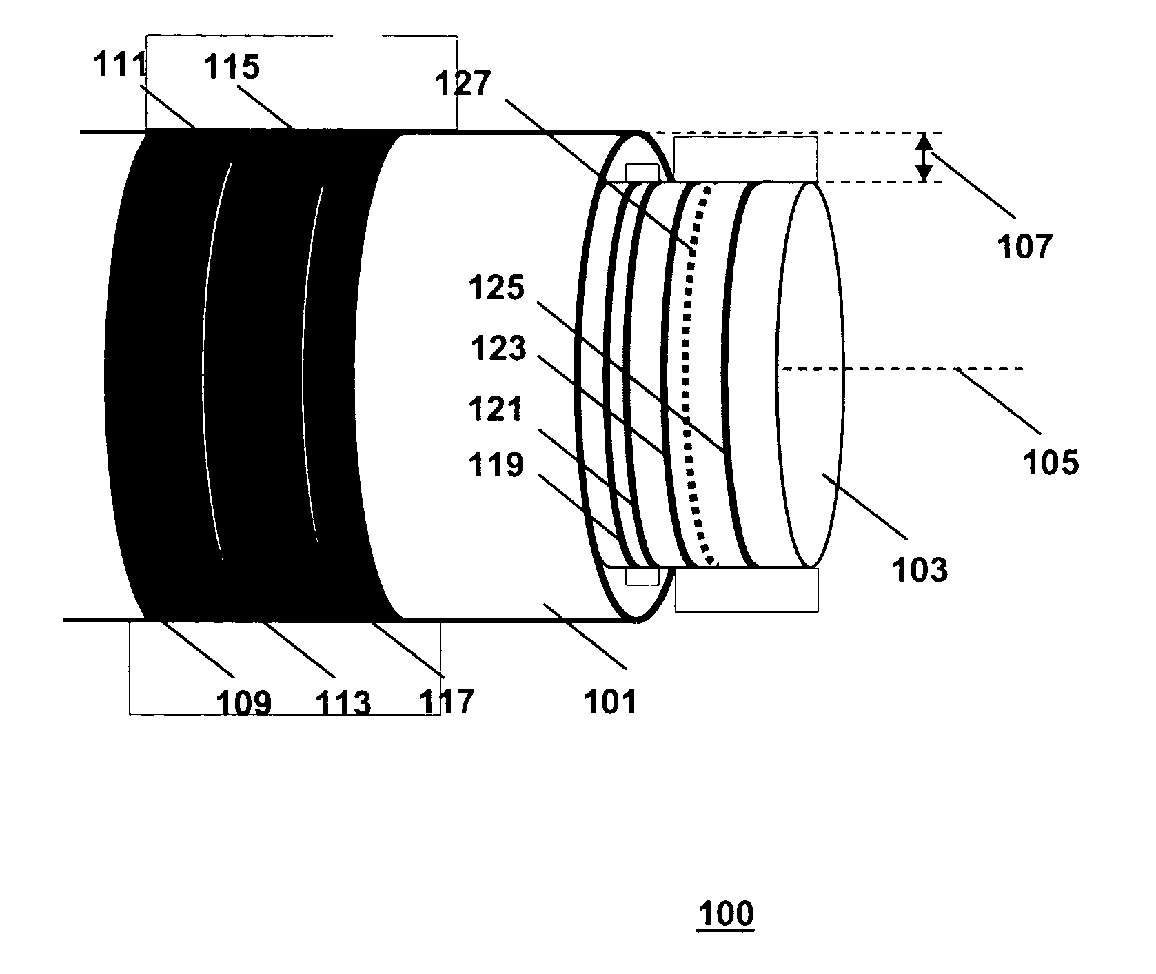
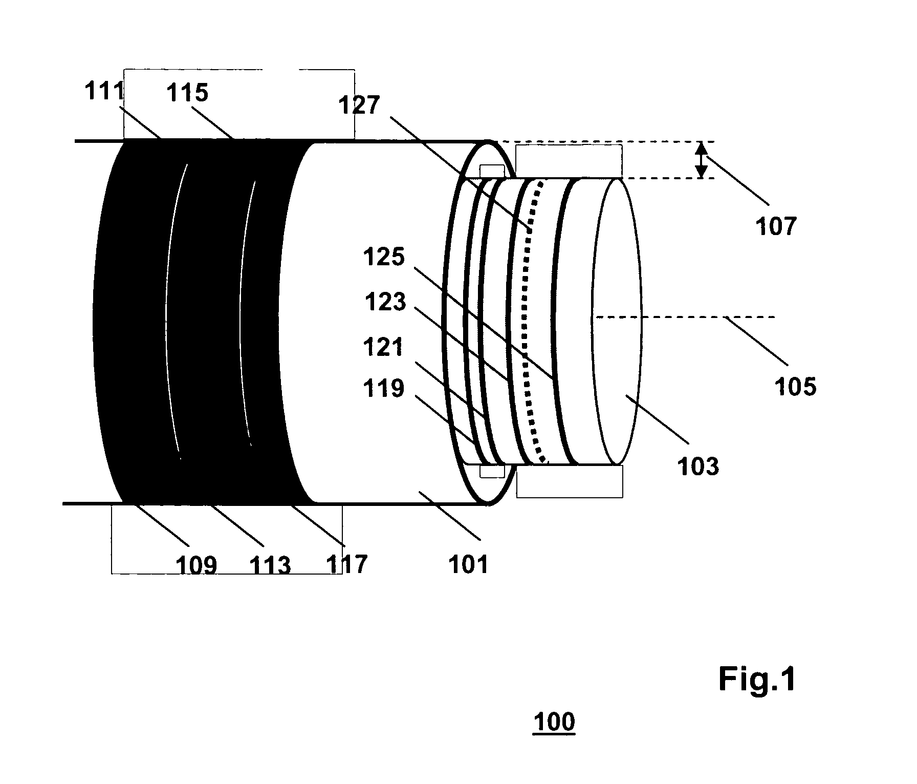
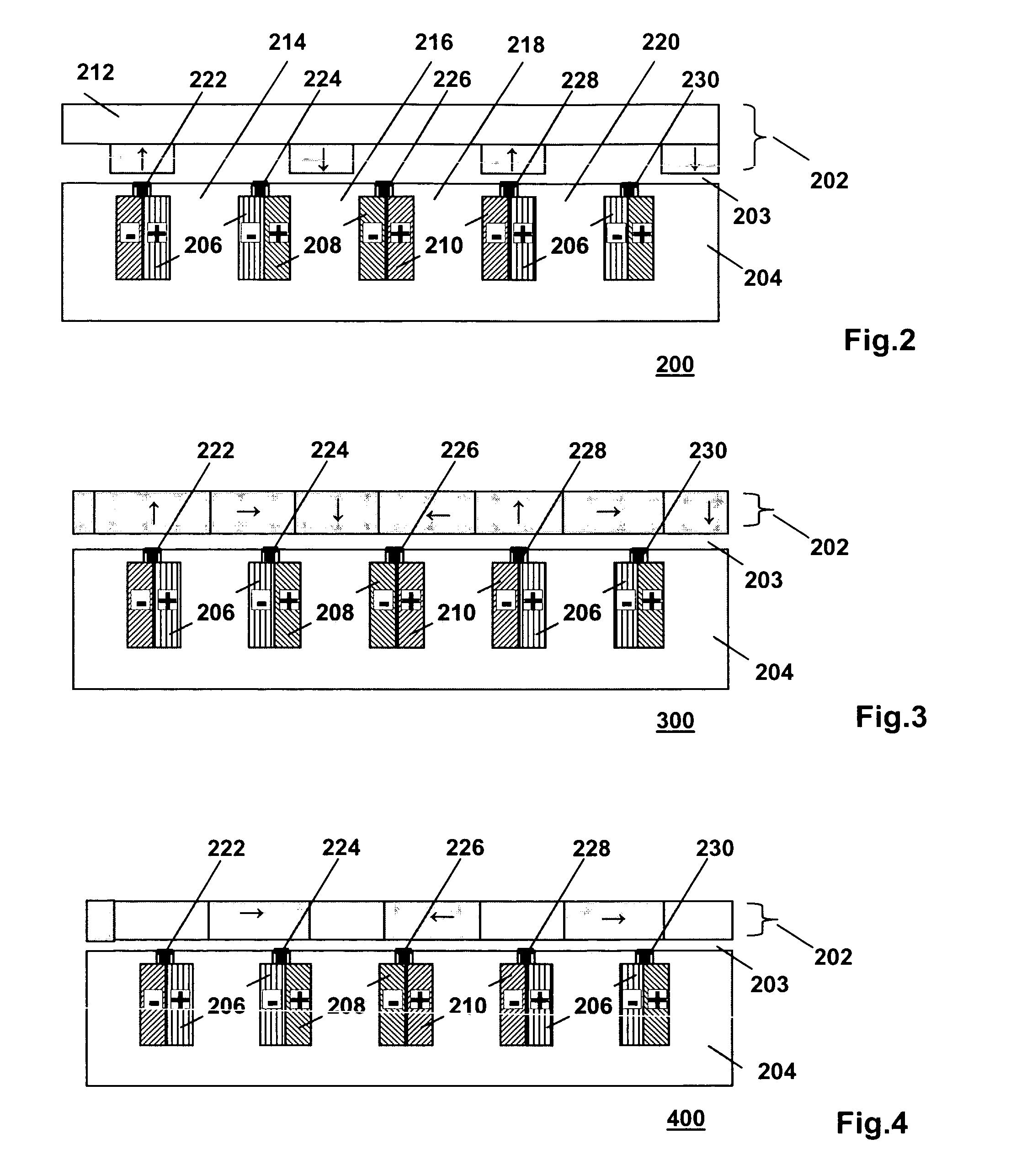
[0025]FIG. 1 is a generic diagram of an actuator 100 of the invention. The actuator 100 comprises first and second components 101 and 103 that are moveable with regard to one another. In the example shown, the components 101 and 103 are coaxial straight cylinders, moveable with respect to one another along their common axes coinciding with a line 105. The width of the gap between the components 101 and 103 is indicated with reference numeral 107. The components 101 and 103 are kept properly aligned with respect to one another by means of a sliding bearing (not shown) present in the space between the components 101 and 103. An array of permanent magnets 109, 111, 113, 115 and 117, is arranged on one of the components 101 and 103, in this example on the component 101. The array extends in a direction parallel to the line 105, i.e., in the axial direction. The other one of the components 101 and 103, in this example the component 103, is made of a ferromagnetic material, and accommodat...


PUM


Abstract

An electromagnetic actuator (100) comprises magnets (109, 111, 113, 115, 11), and a ferromagnetic structure (103) accommodating control conductors (118, 121, 123, 125). The magnets and the structure can move with respect to one another under control of control currents in the control conductors. The magnetic field in a gap (107) between the magnets and the ferromagnetic structure is oriented perpendicular to the direction of relative movement. The structure (103) accommodates damping conductors (127) that form closed loops of an electrically conductive material, different from the ferromagnetic material. The damping conductors (127) provide a damping force induced by the relative movement.

Description

FIELD OF THE INVENTION[0001]The invention relates to an electromagnetic actuator, to a suspension system with at least one such electromagnetic actuator, and to a vehicle comprising a suspension system with at least one such electromagnetic actuator.BACKGROUND ART[0002]A linear actuator imparts a motion of an object along a linear path, e.g., back and forth, by means of applying a force to the object directed along the path traversed by the object. In an electromagnetic actuator, the force is generated through the interaction between a magnetic field and actively controlled electric currents flowing in conductors. The conductors are mounted at a piece of ferromagnetic material that is moveable with respect to the magnets generating the magnetic field.[0003]The object is attached, or otherwise mechanically coupled, to either the piece of ferromagnetic material or the magnets. The ferromagnetic material serves to concentrate the flux of the magnetic field, thereby increasing the magne...

Claims


Application Information

Patent Timeline
IPC IPC(8): F16F15/03B60G17/015H01F7/06
CPCB60G11/00H02K7/104B60G15/00B60G17/0157B60G2202/16B60G2202/422B60G2202/44B60G2202/442F16F15/035H01F7/066H02K41/025H02K41/031H02K21/04H02K1/278B60G13/02H02K1/2783
Inventor GYSEN, BART LUDO JOZEFPAULIDES, JOHANNES JACOBUS HUBERTUSLOMONOVA, ELENA ANDREEVNAENCICA, LAURENTIUVAN LEEUWEN, BERNARDUS GERARDUS
Owner TECH UNIV EINDHOVEN
Learn More