Bypass and protection circuit for a solar module and method of controlling a solar module

a protection circuit and solar module technology, applied in the field of solar technology, can solve the problems of solar modules presenting a danger to their environment, solar modules may be damaged, and the voltage present at said cells will revers

Inactive Publication Date: 2012-08-02
FRAUNHOFER GESELLSCHAFT ZUR FOERDERUNG DER ANGEWANDTEN FORSCHUNG EV
View PDF1 Cites 120 Cited by
  • Summary
  • Abstract
  • Description
  • Claims
  • Application Information

AI Technical Summary

Benefits of technology

[0012]According to an embodiment, bypass and protection circuit for a solar module in a series connection of a plurality of solar modules may have: an input for connecting the solar module; an output for connection with the series connection; a bypass element connected in parallel to the output; and a separating element connected between the input and the output and configured to control the connection between the input and the output; wherein the separating element is configured to control a connection between the input and the output in dependence on whether the solar module associated with the circuit is completely or partially shaded, or whether the solar module associated with the circuit is to be switched on or off.

Problems solved by technology

In the operation of solar modules various situations occur wherein either the solar modules no longer work at the optimum operating point, or wherein damaging of the solar modules may occur due to internal or external conditions.
Also, situations may arise wherein solar modules represent a danger to their environment.
In the event of a series connection of solar cells, in the event of inhomogenous illumination / partial shading or even in the event of different properties of the solar cells, in particular of the short-circuit current, the problem arises that, on the one hand, the cells in question determine the current flow in the overall circuit, and on the other hand, the voltage present at said cells will reverse, i.e. they will turn into load and in the worst case may be damaged.
In accordance with their forward voltage and the current flowing through, a power dissipation of several watts per diode will result, which in the event that shading persists over a relatively long period of time will lead to intense heating of the component.
Said heating will adversely affect the surrounding module components, such as the connecting box, the connecting cable or the modular structure, and in the worst case the components or the bypass diode themselves will be damaged.
However, this leads to the problem that, in the event of shading, only the very low voltage dropping across the active bypass element will be available for driving the bypass element, so that in accordance with the teachings of DE 10 2005 036 153 B4, a charging circuit will additionally be provided which is arranged in connection with an isolating circuit so as to convert transduce the available voltage, which is within the range of millivolts, to a suitable control voltage in the range of 10 to 15 V. Thus, this approach involves a large amount of effort in terms of circuit engineering, in particular in connection with realizing the charging circuit, for example in the form of a choke or reverse transducer or in the implementation as a low-voltage charge pump.
This renders realization of an active bypass and protection circuit as an integrated circuit more complicated and more expensive.
In addition, solar modules have the property that they will produce electric voltage as long as they are irradiated, which means that they cannot be switched off.
What is also problematic is the often high solar generator voltage of several hundred volts in the event that a house having a solar generator mounted on its roof catches fire.
Commercial solar modules do not have the possibility of being switched off.
However, this does not the solve the fundamental problem, since this approach only switches those lines into a voltage-free state which continue behind this unit, but a high voltage will again arise when the module connection on the roof is separated.
The solution suggested here by using a series switch is disadvantageous since said series switch will be adapted to the maximum system voltage in terms of its voltage-sustaining capability, for example to up to 1000 V, since with a series connection of many modules it cannot be ensured that all of the switches will open synchronously.
Such a switch is expensive and will invariably produce a large power dissipation due to its comparatively high on-resistance, and it will lead to the problems described above with regard to the heat generation and the risk of damage associated therewith.
The solution using a parallel switch also exhibits the above-mentioned disadvantages of expensive provision of the supply voltage that may be used, and further has the disadvantage that short-circuit operation of the module will increase the likelihood of damage being caused by so-called “hotspots”.

Method used


Image

  • Bypass and protection circuit for a solar module and method of controlling a solar module
  • Bypass and protection circuit for a solar module and method of controlling a solar module
  • Bypass and protection circuit for a solar module and method of controlling a solar module

Examples


Embodiment Construction

[0034]In the following description of the embodiments of the invention, elements which are identical or have identical actions are provided with identical reference numerals.

[0035]Embodiments of the invention provide a bypass and protection circuit which[0036]exploits the advantages of active switching elements for reducing the heat evolution in the event of shading and for optionally switching on solar modules in a targeted manner, but at the same time exhibits a clearly reduced effort involved in providing the control voltage that may be used internally,[0037]operates the shaded solar cells in an open-circuit condition rather than in a short circuit,[0038]is compatible with commercial system components, such as DC-AC inverters, and[0039]may be realized with low-loss and inexpensive structural components having low voltage-sustaining capability.

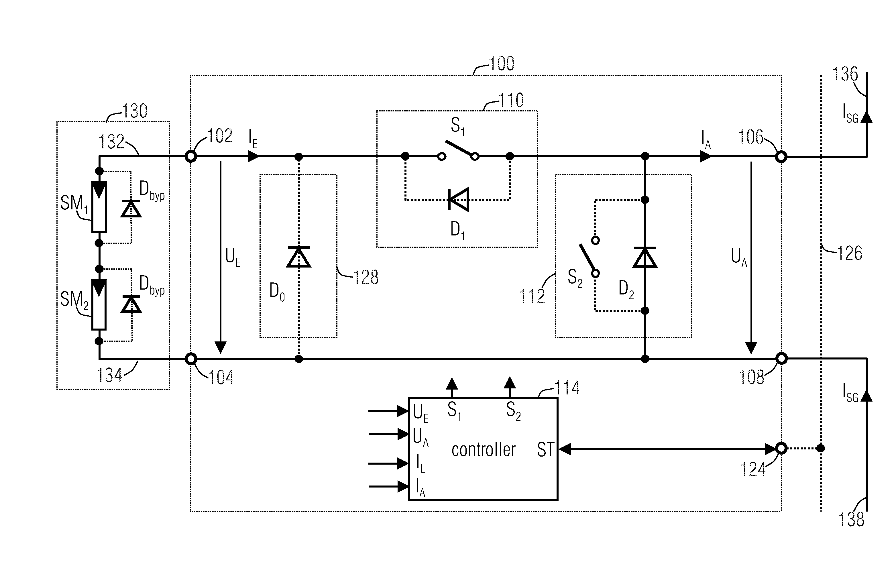
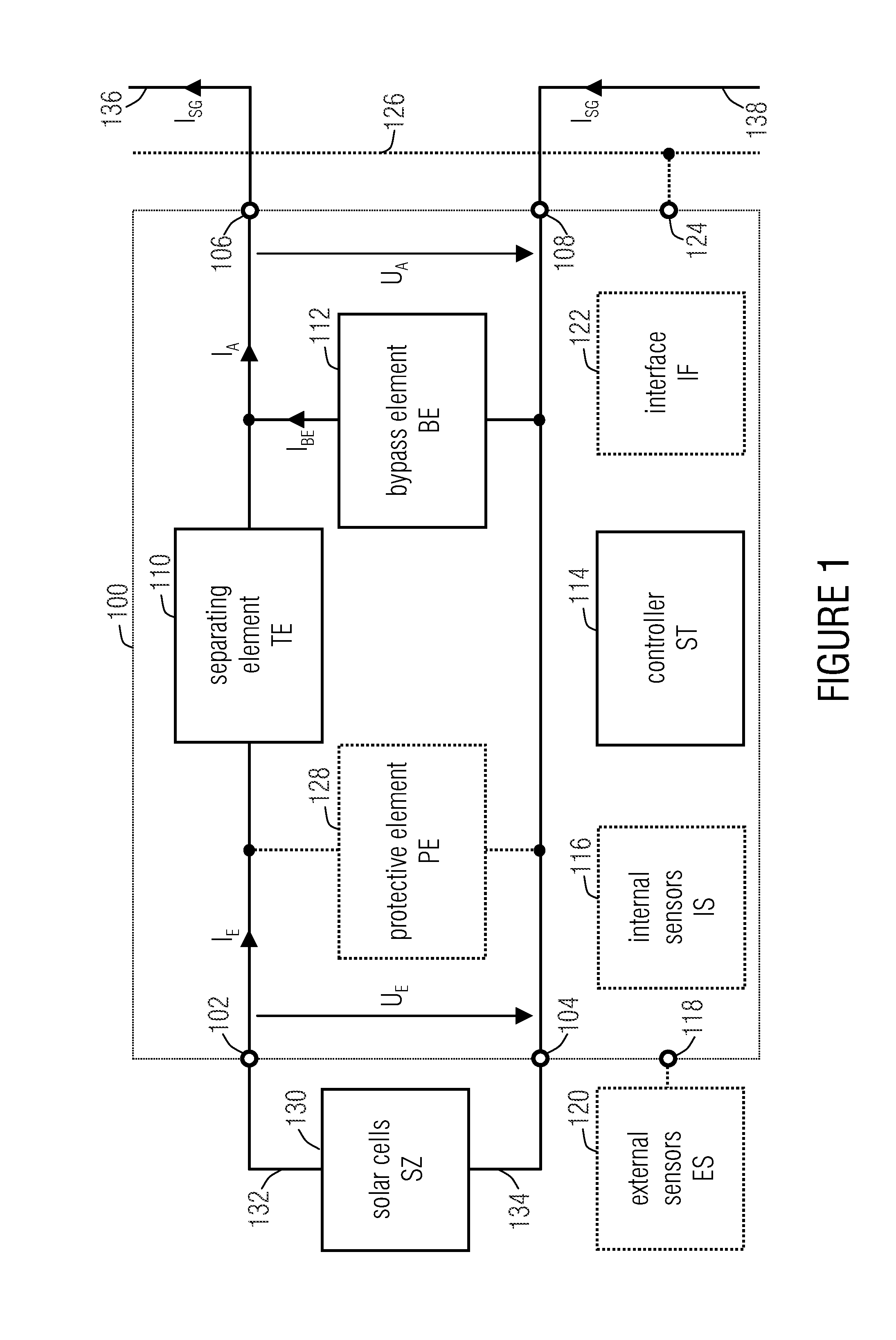
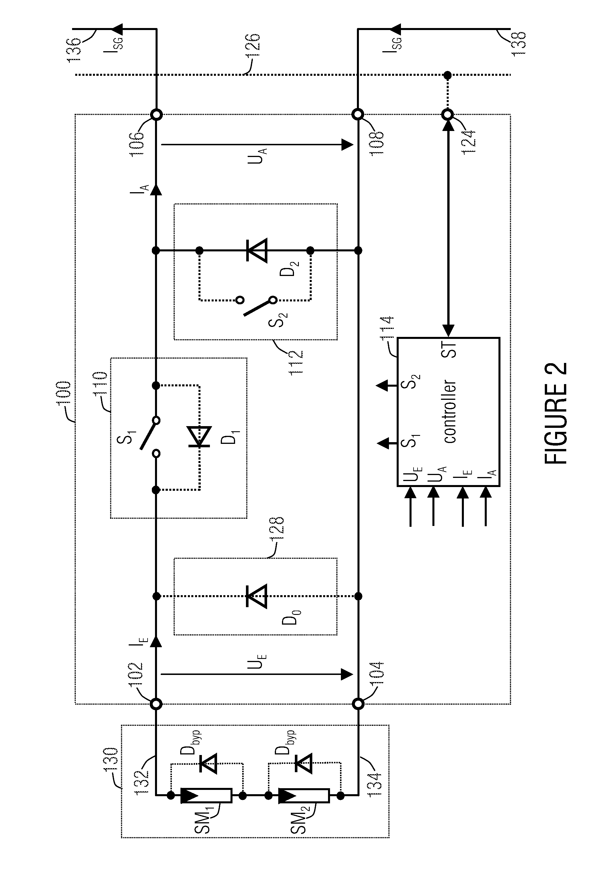
[0040]FIG. 1 shows a block diagram of a bypass and protection circuit 100 in accordance with an embodiment of the invention. The bypass and...


PUM


Abstract

A bypass and protection circuit for a solar module includes an input for connecting the solar module, an output, a bypass element connected in parallel to the output, and a separating element connected between the input and the output and configured to control the connection between the input and the output. The separating element is configured to control a connection between the input and the output in dependence on whether the solar module associated with the circuit is completely or partially shaded, or whether the solar module associated with the circuit is to be switched on or off.

Description

CROSS-REFERENCE TO RELATED APPLICATIONS[0001]This application is a continuation of copending International Application No. PCT / EP2010 / 062419, filed Aug. 25, 2010, which is incorporated herein by reference in its entirety, and additionally claims priority from German Applications Nos. DE 102009038601-7, filed Aug. 26, 2009, and DE 102009049922-9, filed Oct. 19, 2009, both of which are incorporated herein by reference in their entirety.BACKGROUND OF THE INVENTION[0002]The present invention relates to the field of solar technology, and in particular to a bypass and protection circuit for a solar module as well as to a method of controlling a solar module bypassed by a bypass element.[0003]In the operation of solar modules various situations occur wherein either the solar modules no longer work at the optimum operating point, or wherein damaging of the solar modules may occur due to internal or external conditions. Also, situations may arise wherein solar modules represent a danger to t...

Claims


Application Information

Patent Timeline
Patent Type & Authority Applications(United States)
IPC IPC(8): H01H35/00
CPCH01L31/02021Y02E10/56H02H3/023
Inventor SCHMIDT, HERIBERTROTH, WERNER
Owner FRAUNHOFER GESELLSCHAFT ZUR FOERDERUNG DER ANGEWANDTEN FORSCHUNG EV
Why Eureka
Try Eureka