High Torque Density and Low Torque Ripple Actuator System

a technology of actuator system and high torque density, applied in the direction of dynamo-electric machines, synchronous generators, structural associations, etc., can solve the problems of high cost, high system size, and sacrifice of other operating characteristics, and achieve low torque ripple, high torque to ampere ratio, and optimal operating characteristics

Inactive Publication Date: 2012-08-02
GM GLOBAL TECH OPERATIONS LLC
View PDF4 Cites 9 Cited by
  • Summary
  • Abstract
  • Description
  • Claims
  • Application Information

AI Technical Summary

Benefits of technology

[0003]An advantage of an embodiment of the invention is a permanent magnet electric machine drive system that provides optimal op

Problems solved by technology

However, achieving a respective specific operating characteristic typically results in the sacrifice of other operating characteristics.
While inverter-based motor driv

Method used


Image

  • High Torque Density and Low Torque Ripple Actuator System
  • High Torque Density and Low Torque Ripple Actuator System
  • High Torque Density and Low Torque Ripple Actuator System

Examples


Embodiment Construction

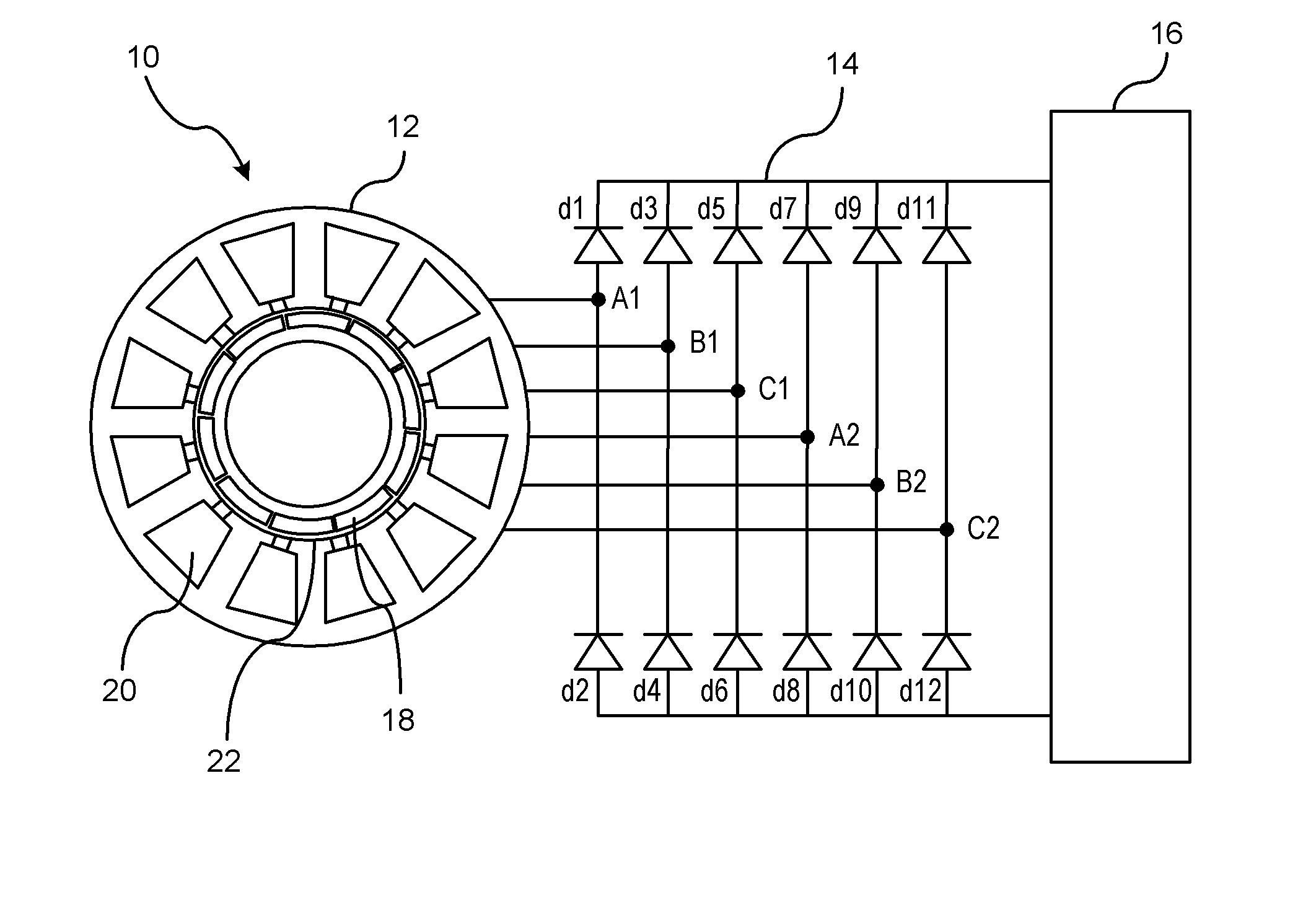
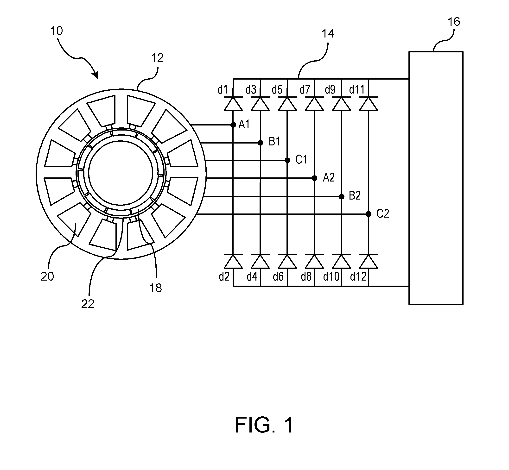
[0016]Referring to FIG. 1 there is shown a high-torque actuator system 10 that generates a low torque ripple. The high-torque actuator system 10 includes a permanent magnet electric machine 12 coupled to a diode bridge 14 and a power control unit 16. The high-torque actuator system 10 as described herein may be used for devices and systems that require high torque and fast response times such as semi-active or active suspension systems, electric power steering systems, or electromechanical braking systems. The high-torque actuator system 10 as described herein achieves a low torque ripple utilizing the diode bridge 14 and a simplified power control unit 16. The power control unit is used to control power (i.e. torque) flow from the PM machine to the electrical load. Power control unit may be buck, buck boost and boost topologies. The permanent magnet electric machine 12 includes a plurality of permanent magnets 18 spaced from a stator 20 that includes a plurality of stator windings....


PUM


Abstract

A permanent magnet electric machine drive system that includes a plurality of magnets for generating a first magnetic field and a stator is disposed radially outward from the plurality of magnets for generating a magnetic field. The stator includes a plurality of stator poles separated by slots with each respective stator pole having a concentrated winding with a respective number of turns formed around each respective stator pole. Each respective concentrated winding within the stator comprising non-overlapping phases. The concentrated windings form a dual three-phase winding configuration that includes a first set of three-balanced phase windings and a second set of three-balanced phase windings. The first set of three-balanced phase windings is phase shifted in the range of 15 to 45 electrical degrees from the second set of three-balanced phase windings for reducing the torque ripple.

Description

BACKGROUND OF INVENTION[0001]An embodiment relates generally to permanent magnet motor drive system.[0002]Electric machines are typically designed to achieve a specific operating characteristic. AC electric machines with drag cup rotors have very low inertia properties. AC Induction machines typically exhibit ripple-free torque properties, whereas conventional AC brushless permanent magnet synchronous machines exhibit high torque to ampere ratios. However, achieving a respective specific operating characteristic typically results in the sacrifice of other operating characteristics. Inverter-based motor drive systems are used to control speed and torque of the AC motor. While inverter-based motor drive systems may reduce torque ripple, such systems are complex and expensive. Such systems typically are large in size and introduce EMI to the vehicle electrical system.SUMMARY OF INVENTION[0003]An advantage of an embodiment of the invention is a permanent magnet electric machine drive sy...

Claims


Application Information

Patent Timeline
IPC IPC(8): H02K11/04
CPCH02K21/16H02K3/28
Inventor HAO, LEINAMUDURI, CHANDRA S.
Owner GM GLOBAL TECH OPERATIONS LLC
Why Eureka
Try Eureka