Control system for electrochromic device

a control system and electrochromic technology, applied in the direction of instruments, walls, construction, etc., can solve the problems of difficult and costly installation of wires for power and control through the window framing system of the building and the structural system/support of the building

Active Publication Date: 2012-08-02
SAGE ELECTROCHROMICS
View PDF4 Cites 199 Cited by
  • Summary
  • Abstract
  • Description
  • Claims
  • Application Information

AI Technical Summary

Benefits of technology

[0007]In another embodiment, photovoltaic module and the electronics module are combined into a single unit. In another embodiment, combined photovoltaic and electronics module have a thickness less than about 10 mm.
[0008]In another embodiment, electronics module responds to s

Problems solved by technology

When installing electrochromic glazings, installing wires for power and control through the building's window framing system and the building's structural systems/supports can be difficult an

Method used


Image

  • Control system for electrochromic device
  • Control system for electrochromic device
  • Control system for electrochromic device

Examples


Embodiment Construction

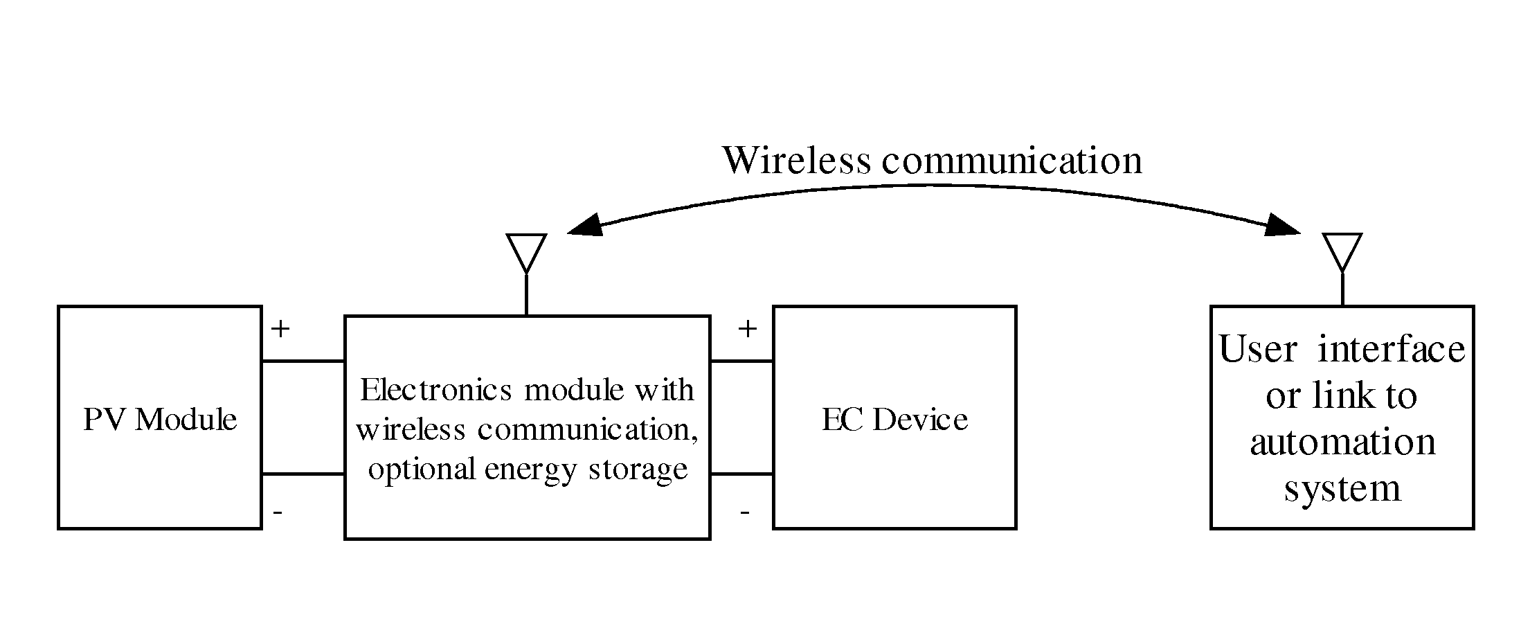
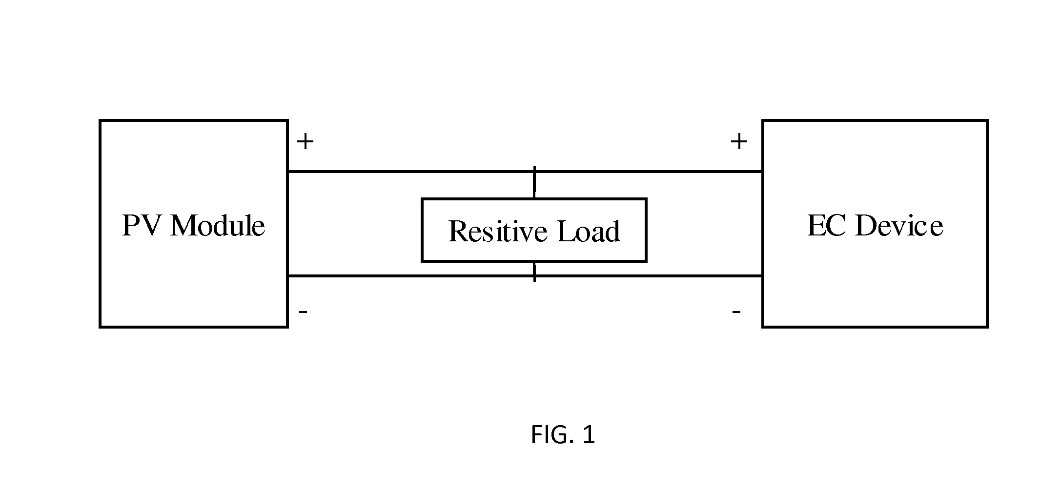
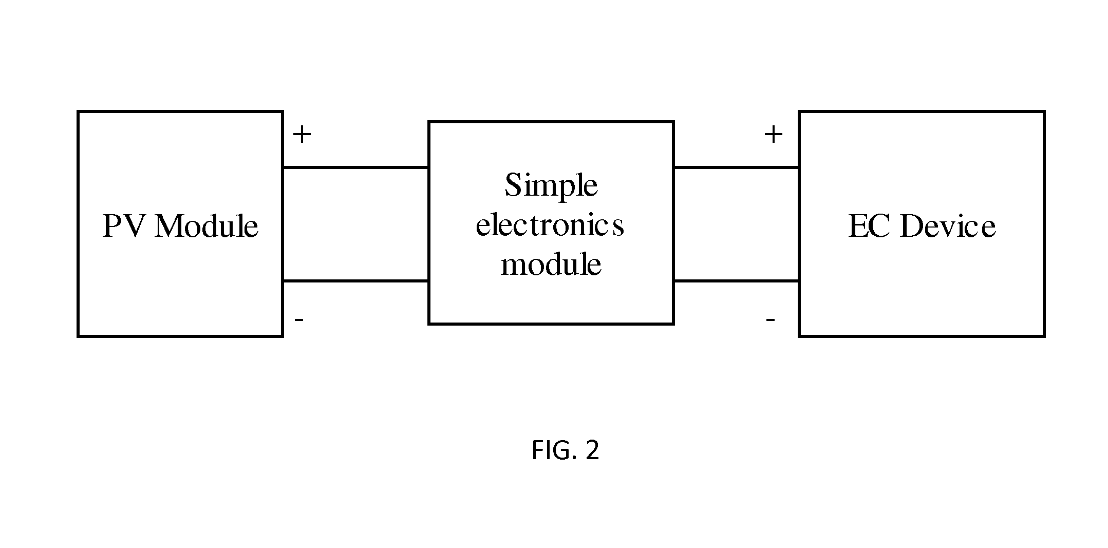
[0032]The present invention is directed to electrochromic systems comprising an electrochromic glazing or insulated glazing unit (hereinafter “IGU”), a photovoltaic (hereinafter “PV”) module for supplying power to the electrochromic glazing or IGU, and an electronics module in communication with either the electrochromic glazing unit and / or photovoltaic module.

[0033]Insulated glazing units, as that term is used herein, means two or more layers of glass separated by a spacer along the edge and sealed to create a dead air (or other gas, e.g., argon, nitrogen, krypton) space between the layers. The terms “electrochromic glazing” or “IGU” are used interchangeably herein. The electrochromic glazing may have a laminate structure (see copending U.S. applications Ser. Nos. 13 / 040,787 and 13 / 178,065, the disclosures of which are hereby incorporated by reference herein in their entirety).

[0034]The electrochromic glazing and / or IGU are typically used for architectural purposes, e.g. architectu...


PUM


Abstract

The present invention is directed to electrochromic systems comprising an electrochromic glazing or insulated glazing unit, a photovoltaic module for supplying power to the electrochromic glazing or IGU, and an electronics module in communication either the electrochromic glazing and/or photovoltaic module.

Description

CROSS-REFERENCE TO RELATED APPLICATIONS[0001]This application claims the benefit of the filing date of U.S. Provisional Patent Application No. 61 / 435,391 filed Jan. 24, 2011, the disclosure of which is hereby incorporated herein by reference.BACKGROUND OF THE INVENTION[0002]Electrochromic glazings include electrochromic materials that are known to change their optical properties, such as coloration, in response to the application of an electrical potential, thereby making the device more or less transparent or more or less reflective. Typical prior art electrochromic devices include a counter electrode layer, an electrochromic material layer which is deposited substantially parallel to the counter electrode layer, and an ionically conductive layer separating the counter electrode layer from the electrochromic layer respectively. In addition, two transparent conductive layers are substantially parallel to and in contact with the counter electrode layer and the electrochromic layer. M...

Claims


Application Information

Patent Timeline
IPC IPC(8): G02F1/163G02F1/153
CPCG02F1/157E04B2/88G02F2001/13324G02F1/163G02F1/13324
Inventor PODBELSKI, LOUGREER, BRYAN D.SNYKER, MARK O.
Owner SAGE ELECTROCHROMICS
Why Eureka
Try Eureka