Kneading segment and kneading equipment

a technology of kneading equipment and kneading segment, which is applied in the direction of clay mixing apparatus, mixing/kneading with horizontally mounted tools, transportation and packaging, etc. it can solve the problems of easy clogging of materials, achieve convenient material flow, prevent clogging and scraping, and facilitate material flow

Active Publication Date: 2012-08-02
KOBE STEEL LTD
View PDF2 Cites 23 Cited by
  • Summary
  • Abstract
  • Description
  • Claims
  • Application Information

AI Technical Summary

Benefits of technology

[0031]Here, making each of the radii of curvature of the first flow surface and the second flow surface to be substantially twice a clearance between wing portions means a range of approximately 1.5 times or more and less than 2.5 times. In a case of the range of 1.5 times or more and less than 2.5 times, an assured and sufficient effect that facilitates flow of material that is located at the part where the wing leading end surface and wing surface connect with each other is confirmed, and also an assured and sufficient effect that facilitates flow of material that is located at the part where the wing surface and the wing side surface connect with each other is confirmed.

Problems solved by technology

Thus, it becomes difficult for the material to pass this intersecting part, which causes the stay.
More specifically, if the wing surface and wing side surface

Method used


Image

  • Kneading segment and kneading equipment
  • Kneading segment and kneading equipment
  • Kneading segment and kneading equipment

Examples


Embodiment Construction

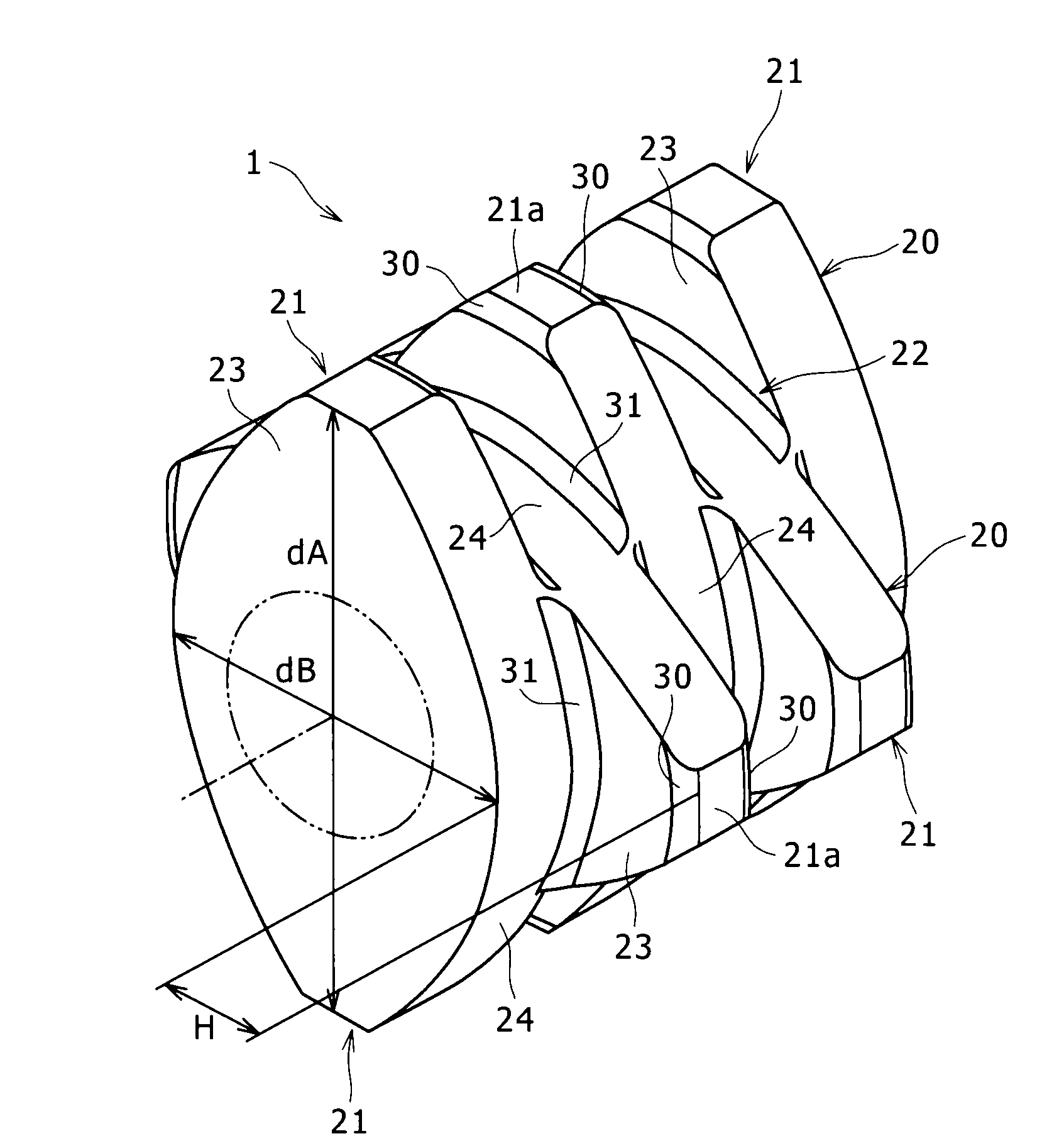
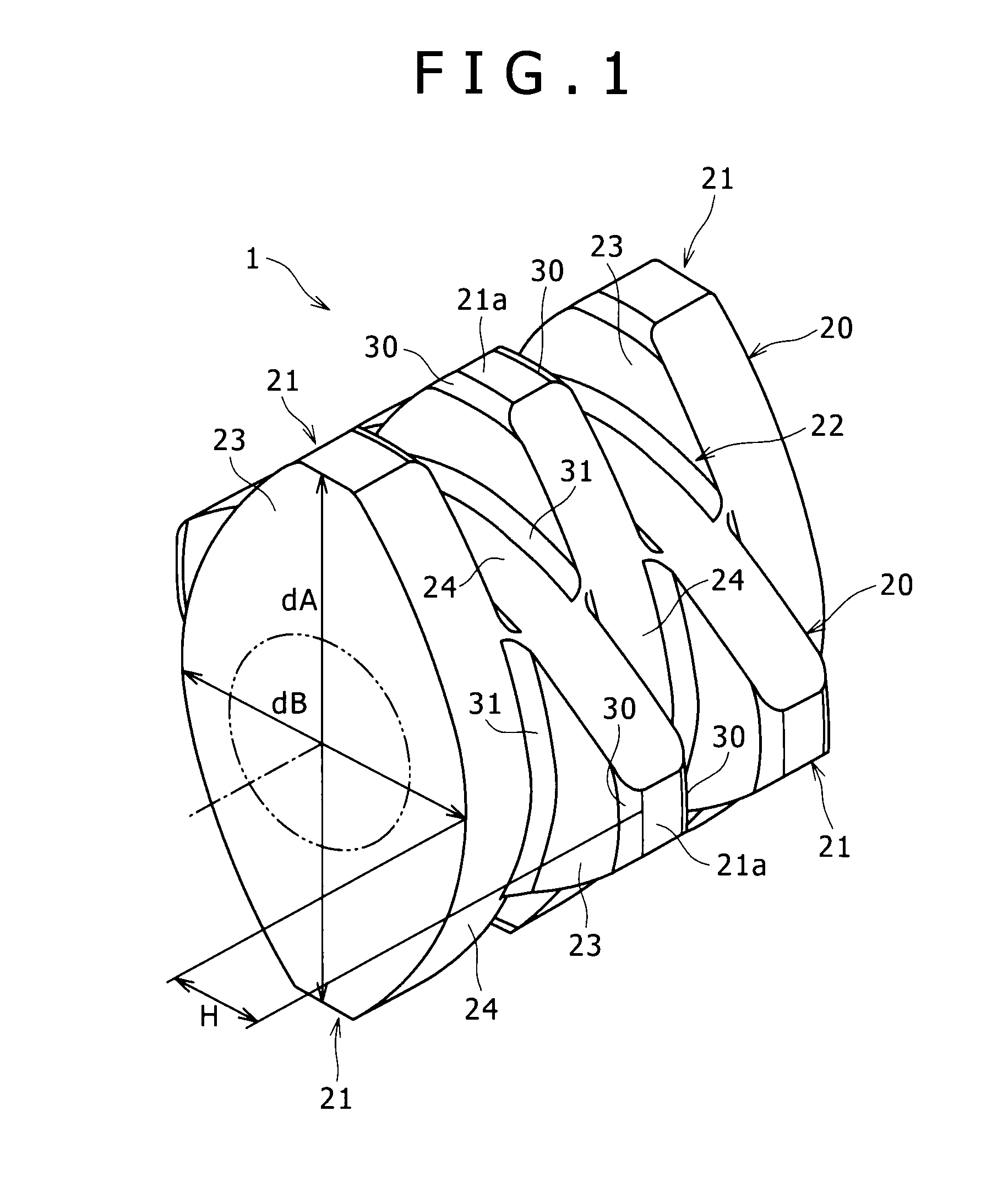
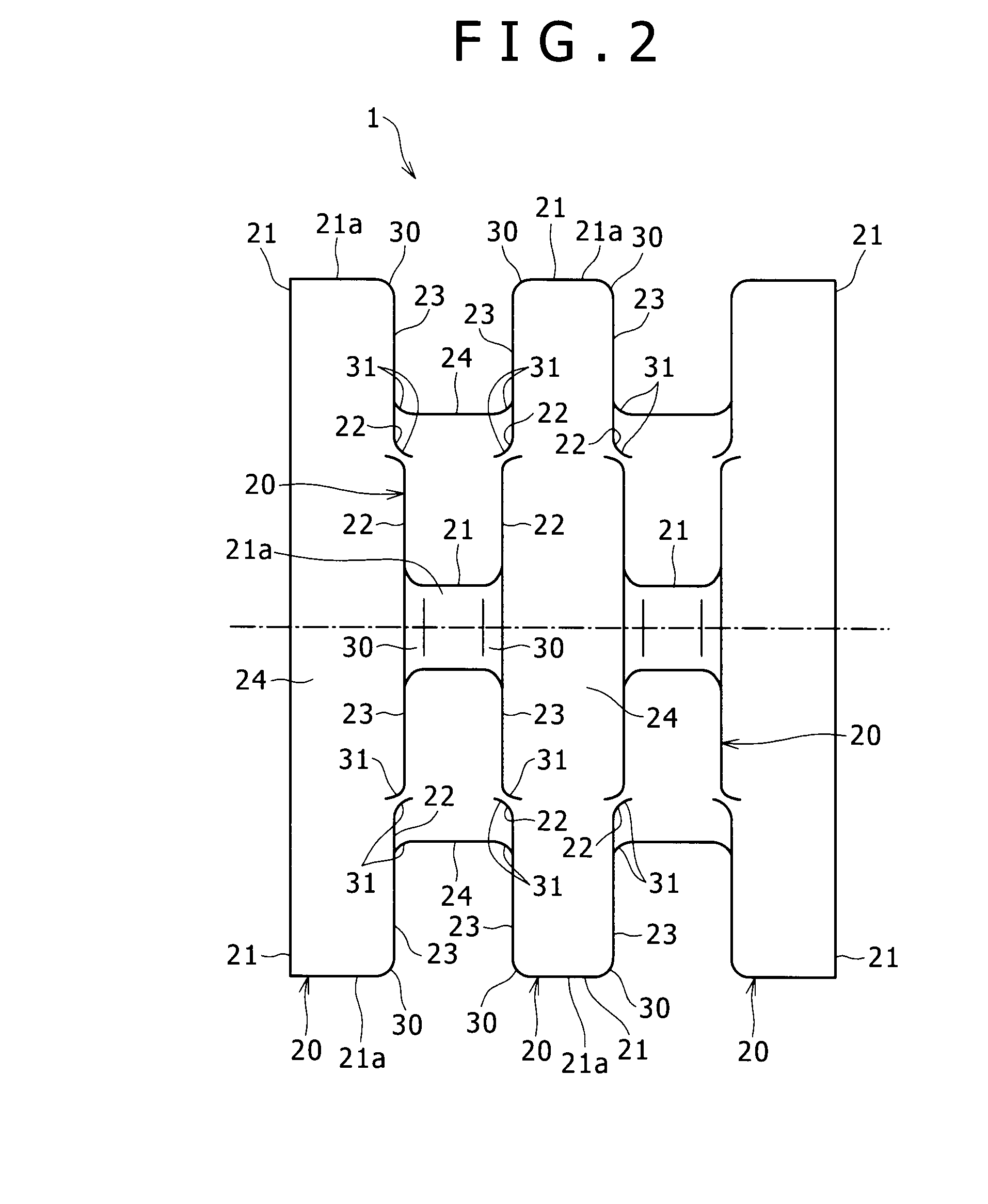
[0042]Hereinafter, embodiments of the present invention will be explained with reference to the drawings.

[0043]FIGS. 1 to 5 show a first embodiment of a kneading segment 1 according to the present invention. FIG. 6 is a lateral cross-sectional view schematically showing kneading equipment 2, in which the kneading segment 1 can be employed.

[0044]As shown in FIG. 6, the kneading equipment 2 has a barrel 4 including a hollow space inside thereof, and plural parallel kneading screws 3 that are provided in the hollow space of this barrel 4. The kneading segment 1 is provided at a part, located along the axial direction, of each kneading screw 3. The kneading segments 1 are provided at the same positions, along the axial direction, of the kneading screws 3, and thus are disposed side by side in the kneading equipment 2 (in the barrel 4).

[0045]In the kneading equipment 2, the kneading screws 3 rotate in the same direction in the barrel 4 so as to continuously knead material and simultaneou...


PUM

PropertyMeasurementUnit
Fractionaaaaaaaaaa
Thicknessaaaaaaaaaa
Flow rateaaaaaaaaaa

Abstract

A kneading segment includes plural wing portions integrally formed along an axis such that angles, around the axis, of the plural wing portions are shifted. At a part of a leading end of each wing portion where a wing leading end surface and a wing surface connect with each other, a first flow surface facilitates flow of material between the wing leading end surface and the wing surface. At a part of a base end of each wing portion where a wing surface and a wing side surface of another wing portion adjacent to each wing portion connect with each other, a second flow surface facilitates flow of material between the wing surface and the wing side surface. Since such a configuration prevents material from staying between parallel kneading segments, impurities are prevented and will not mix into normally kneaded material.

Description

BACKGROUND OF THE INVENTION[0001]1. Field of the Invention[0002]The present invention relates to a kneading segment, and kneading equipment, in which this kneading segment is employed.[0003]2. Description of the Related Art[0004]In general kneading equipment such as an extruding machine and a kneading machine, pellets of polymer resin serving as a base material, and powder additives are supplied into a barrel, the base material and additives are simultaneously kneaded and fed to the downstream side of the barrel by plural (in most cases, two as a pair) parallel kneading screws that are inserted in the barrel, thereby a composite resin material such as a plastic compound is manufactured.[0005]A kneading segment is provided at a part of each kneading screw employed in kneading equipment, part which is located along the axial direction of the kneading screw. As such kneading segments, there are a rotor segment and a kneading disc segment. As shown in Japanese Patent Application Publica...

Claims


Application Information

Patent Timeline
IPC IPC(8): B01F7/00B01F27/93B01F27/74B29C48/03B29C48/54B29C48/57B29C48/76
CPCB29B7/483B29B7/847B29C47/402B29C47/6031B29C47/767B29C47/0009B29C47/6056B29C48/03B29C48/402B29C48/54B29C48/57B29C48/767B29B7/488B29B7/489B29B7/20B01F27/74
Inventor GENNAI, TATSUOKASAI, SHIGEHIROFUNAHASHI, HIDEO
Owner KOBE STEEL LTD
Why Eureka
Try Eureka