
Spectral magnetic particle imaging

Inactive Publication Date: 2012-08-02
KONINKLIJKE PHILIPS ELECTRONICS NV
View PDF6 Cites 3 Cited by
  • Summary
  • Abstract
  • Description
  • Claims
  • Application Information

AI Technical Summary

Benefits of technology

[0005]It is therefore an object of the present invention to provide means and method to overcome the aforementio

Problems solved by technology

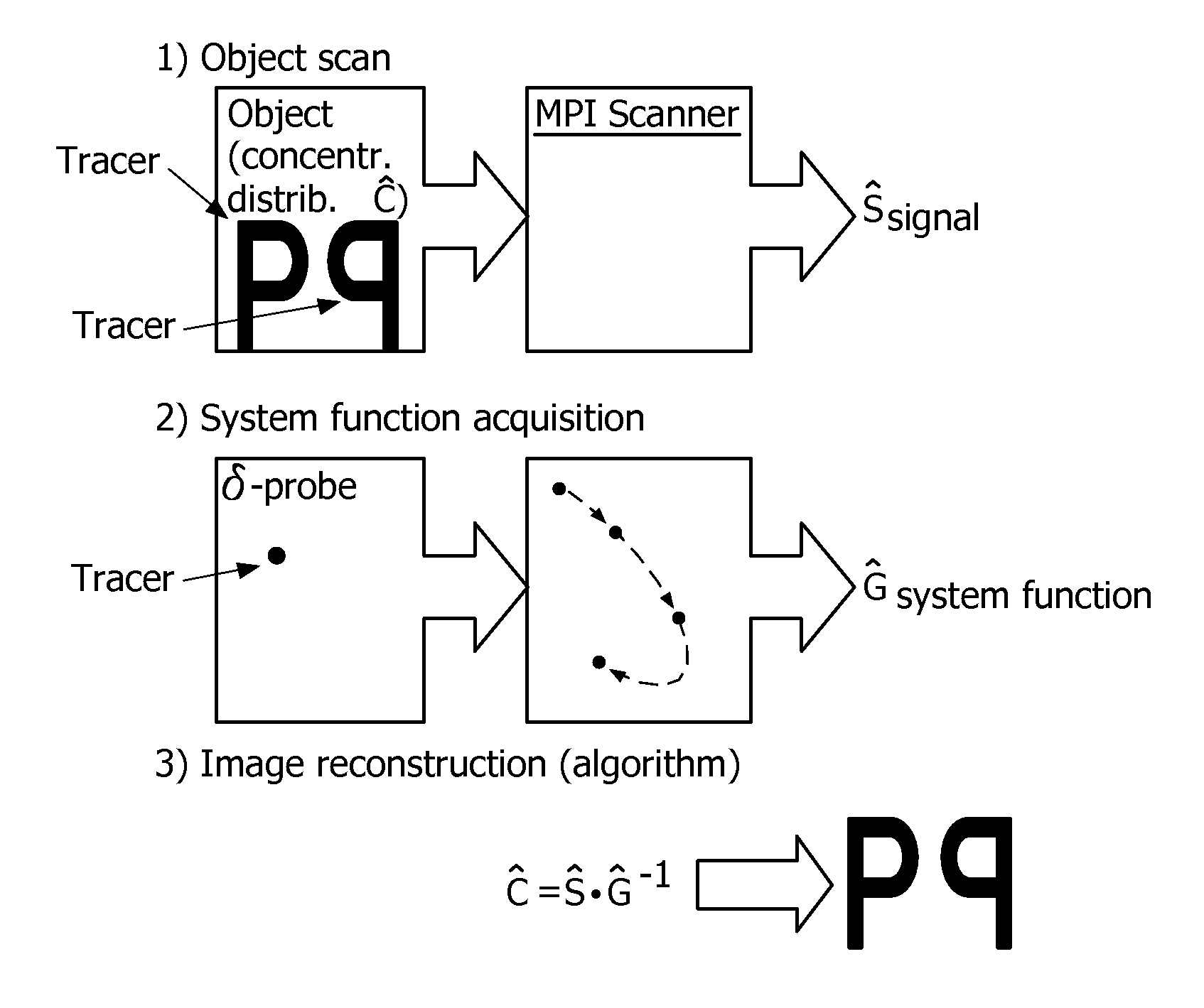
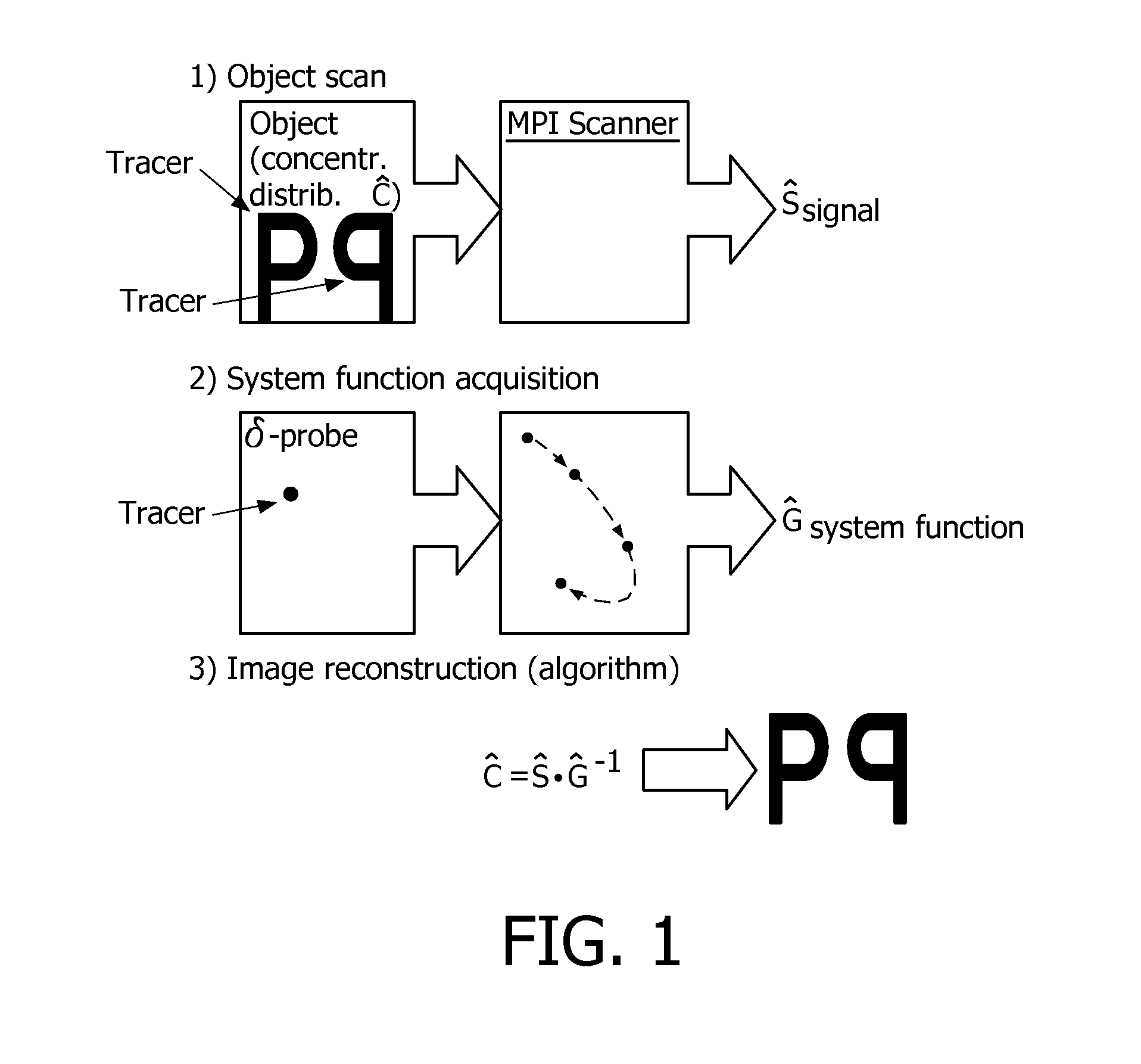
Known magnetic particle imaging techniques result in images that visualize the local concentration distribution of a tracer material in an object, but does not allow for discriminating between different types of tracer materials.
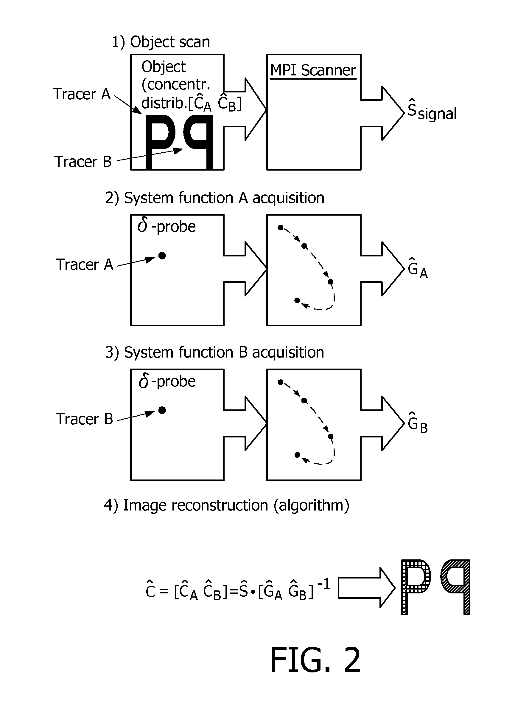
Thus, currently magnetic particle imaging provides information (usually via grey scale images) about the concentration or distribution of one tracer material over the body tissue, but does not enable the discrimination between different tissue types or the detection of different functional areas via two or more tracer materials.

Method used


Image

  • Spectral magnetic particle imaging
  • Spectral magnetic particle imaging
  • Spectral magnetic particle imaging

Examples


example 1

Simulation Study Using 30 Nm and 40 Nm Magnetic Iron Oxide Particles to Determine the Local Concentration Distribution Magnetic Iron Oxide Particles

[0069]In this image simulation study, two types of particles are included: particles described by the Langevin function with diameters of 30 nm and 40 nm, wherein the acquired data was processed using the inventive method. The 2D-object and the reconstructed MPI images are shown on FIG. 4. The local concentration distributions and system functions are labelled according to the aformentioned specification, wherein the indices 30 and 40 represent the size of the corresponding particles. The Signal Ŝ can be calculated using

Ĉ30Ĝ30+Ĉ40Ĝ40=[Ĉ30Ĉ40] [Ĝ30Ĝ40]=Ŝ,

where [. . . ] stands for concatenation along the direction of the positions i. For the system functions discrete positions i=100×100 are used. The number of spectral components taken into account are 5000 (with the same components for both matrices), whereby the matrices Ĝ30 and Ĝ40 have...


PUM

PropertyMeasurementUnit
Particle sizeaaaaaaaaaa
Distributionaaaaaaaaaa

Abstract

The invention relates to the discrimination of spectroscopically different tracer materials by magnetic particle imaging (MPI), based on the differences of the MPI spectral responses of said tracer materials.

Description

FIELD OF THE INVENTION[0001]The present invention refers to contrast agents capable of being detected by magnetic particle imaging (MPI), the use of said contrast agents as well as to a method for detecting said contrast agent by MPI.BACKGROUND OF THE INVENTION[0002]Magnetic particle imaging (MPI) refers to a method to determine the spatial distribution of magnetic particles in an examination zone. Typically, MPI methods require the generation of a magnetic field with a spatial course of the magnetic field strength, which is such that a first partial region with a low magnetic field strength and a second partial region with a higher magnetic field strength are obtained in an examination area. The spatial position of the two partial regions in the examination area are changed so that the magnetization of the particles changes locally. The signals to be recorded are dependent on the magnetization in the examination area. The signals are finally evaluated so as to obtain information ab...

Claims


Application Information

Patent Timeline
IPC IPC(8): A61B5/05A61K49/18A61K49/06
CPCA61B5/0515A61B5/05
Inventor PASMANS, PETER LEONARDUS ELISABETH MARIAMARKOV, DENIS
Owner KONINKLIJKE PHILIPS ELECTRONICS NV
Learn More