Reading and adjusting tool for hydrocephalus shunt valve

a technology of hydrocephalus and shunt valve, which is applied in the direction of suction devices, valve arrangements, thin material handling, etc., can solve the problems of difficult to determine/or adjust the setting of the valve, damage to the brain tissue, and difficulty in determining and/or adjusting the valve setting

Active Publication Date: 2012-08-02
MEDTRONIC XOMED INC
View PDF6 Cites 19 Cited by
  • Summary
  • Abstract
  • Description
  • Claims
  • Application Information

AI Technical Summary

Problems solved by technology

Whatever the cause, over time, this increased CSF pressure causes damage to the brain tissue.
One complication with current adjustable valves is that once implanted, it is difficult to determine the setting of the valve and / or adjust the setting of the valve.
Having more settings for the valve only makes determining and / or adjusting the valve setting more difficult.
By requiring an x-ray, it is time consuming and costly to determine and adjust the valve setting, as well as not being in the best interest of the patient due to x-ray exposure issues.
Another complication with current adjustable valves is compatibility with magnetic resonance imaging (MRI) procedures.
As many current adjustable valves utilize magnets for adjusting and / or determining a valve setting, their function can be disrupted due to interaction of magnetic components in the valve with the applied magnetic field created during the MRI procedure.
In particular, the valve setting can be altered to a random, undesirable setting.
If the valve setting is not returned to the desired setting after the MRI procedure, this situation can be extremely harmful to a patient.

Method used


Image

  • Reading and adjusting tool for hydrocephalus shunt valve
  • Reading and adjusting tool for hydrocephalus shunt valve
  • Reading and adjusting tool for hydrocephalus shunt valve

Examples


Embodiment Construction

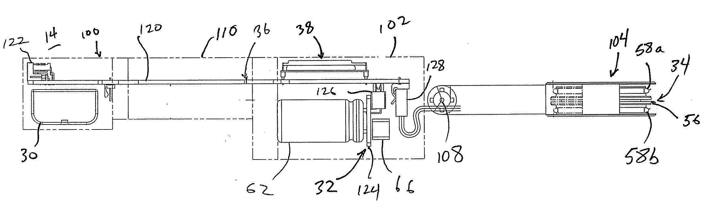
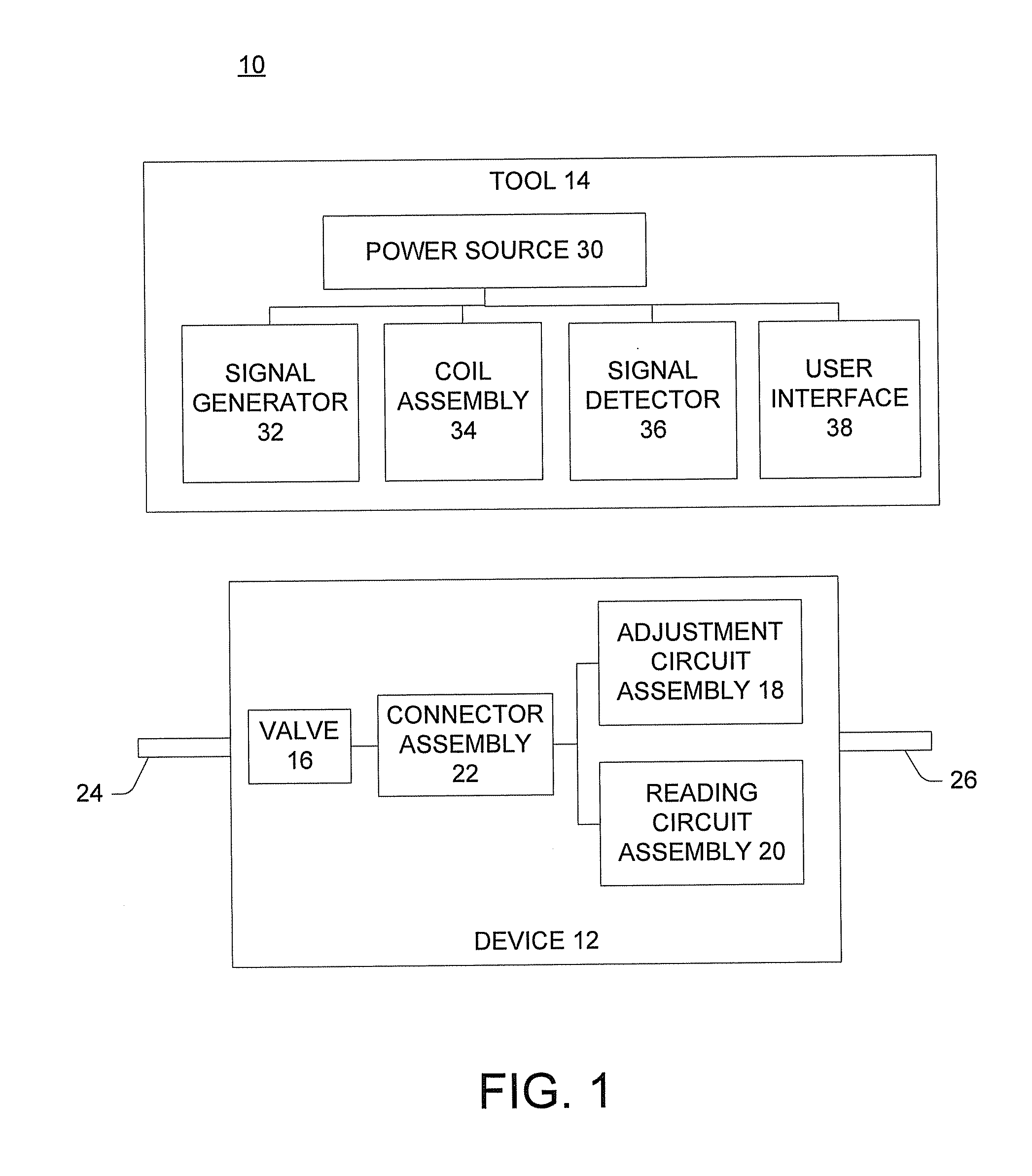
[0020]FIG. 1 is a schematic block diagram of an adjustable shunt system 10 including an implantable flow control device 12 (e.g., a shunt) and an electronic valve reader and adjustment tool 14. In general, device 12 can be implanted in a patient to regulate flow of fluids (e.g., CSF discussed above) within the patient based on a pressure or flow setting (also known as a valve setting) for the device 12. Tool 14, in turn, can be a handheld mechanism configured to subcutaneously read and / or adjust the pressure or flow setting of the device 12 when positioned proximate thereto. In particular, the tool 14 can create an oscillating electromagnetic field that is received by device 12. The field can cause device 12 to adjust the pressure or flow setting and / or provide feedback indicative of a pressure or flow setting as will be discussed below.

[0021]The device 12 includes a valve 16, an adjustment circuit assembly 18, a reading circuit assembly 20 and a connector assembly 22 coupling the v...


PUM


Abstract

A reading and adjustment tool for use with a valve having a pressure or flow setting adjustable to a plurality of pressure or flow settings is disclosed. The tool includes a signal generator and an excitation coil coupled to the signal generator. The signal generator includes an adjustment interface configured to generate an adjustment signal to adjust the pressure or flow setting and a reading interface to generate a reading signal to read the pressure or flow setting of the valve. At least one excitation coil is connected to the signal generator and configured to generate an oscillating electromagnetic field based on one of the adjustment signal and reading signal. A sense coil can include two portions positioned on either side of the at least one excitation coil to determine the pressure or flow setting of the valve.

Description

BACKGROUND[0001]1. Technical Field[0002]This disclosure relates generally to surgically implanted physiological shunt systems and related flow control devices. More particularly, the present disclosure relates to a position indicator and adjustment tool for such shunt systems having variable pressure or flow settings for the one-way flow control valves controlling the flow of Cerebral Spinal Fluid (CSF) out of a brain ventricle and preventing backflow of fluid into the brain ventricle.[0003]2. Description of Related Art[0004]A typical adult has a total of about 120-150 cubic centimeters (cc) of CSF with about 40 cc in ventricles in the brain. A typical adult also produces about 400-500 cc / day of CSF, all of which is reabsorbed into the blood stream on a continuous basis.[0005]Sometimes, the brain produces excess CSF or there can be a blockage of the normal CSF pathways and or absorption sites resulting in a condition known as hydrocephalus. Hydrocephalus is a condition of excessive ...

Claims


Application Information

Patent Timeline
Patent Type & Authority Applications(United States)
IPC IPC(8): A61M1/00
CPCF16K37/0041A61M27/006Y10T137/8242Y10T137/7761
Inventor PRISCO, JOHN R.MURPHY, JOHN MURDOCKHEI, JAMIEMAYOR, LAETITIAJAQUIER, PIERRE
Owner MEDTRONIC XOMED INC
Why Eureka
Try Eureka