Capacity control valve

a technology of capacity control and valve body, which is applied in the direction of pump control, positive displacement liquid engine, pump control, etc., can solve the problems of affecting the designated control function of the compressor, affecting the movement of the valve body, and leaking control fluid through sliding parts, so as to achieve the effect of substantially completely preventing leakage between the discharge side and the suction sid

Active Publication Date: 2012-08-09
EAGLE INDS
View PDF1 Cites 30 Cited by
  • Summary
  • Abstract
  • Description
  • Claims
  • Application Information

AI Technical Summary

Benefits of technology

[0032](1) Adopting a bellows-type valve that uses a bellows in the first valving element for opening and closing the discharge-side passage in the capacity control valve allows problems such as the catching of foreign matter in the sliding parts and leakage on the sliding parts, which occur in conventional capacity control valves, to be completely resolved because of the absence of sliding parts between the valving element and the valve body.
[0033](2) The bellows-type valve comprises a main body part in contact with the bearing surface of the discharge-side passage, a bellows in which one end is joined in an airtight manner to the rear surface of the main body part, and a fixing bracket joined in an airtight manner to the other end of the bellows, wherein the fixing bracket is fixed in an airtight manner to a valve body between the first valve chamber and the suction port. Leakage between the discharge side and the suction side can thereby be substantially completely prevented.
[0034](3) The pressure-receiving surface area B1 at the seal diameter of the first valving element and the pressure-receiving surface area C1 at the effective diameter of the bellows of the first valving element are made equal to each other, whereby the discharge pressure Pd acting on the first valving element can be canceled out to prevent the effect thereof, the first valving element can operate without being affected by the discharge pressure Pd, and capacity can be controlled in a stable manner.

Problems solved by technology

This produces defects such as a hindrance to the movement of the valving element 104 when foreign matter is caught in the sliding parts, or an occasional stoppage of operation.
In addition, when the clearance of the sliding parts is increased in order to prevent foreign matter from being caught in this manner, control fluid leaks via the sliding parts, and the designated control function of the compressor is adversely affected.

Method used


Image

  • Capacity control valve
  • Capacity control valve
  • Capacity control valve

Examples


Embodiment Construction

[0040]The modes of working the capacity control valve according to the present invention are described in detail below with reference to the drawings, but various changes, modifications, and improvements are possible within the scope of the present invention based on the knowledge of one skilled in the art, without limiting the interpretation of the present invention.

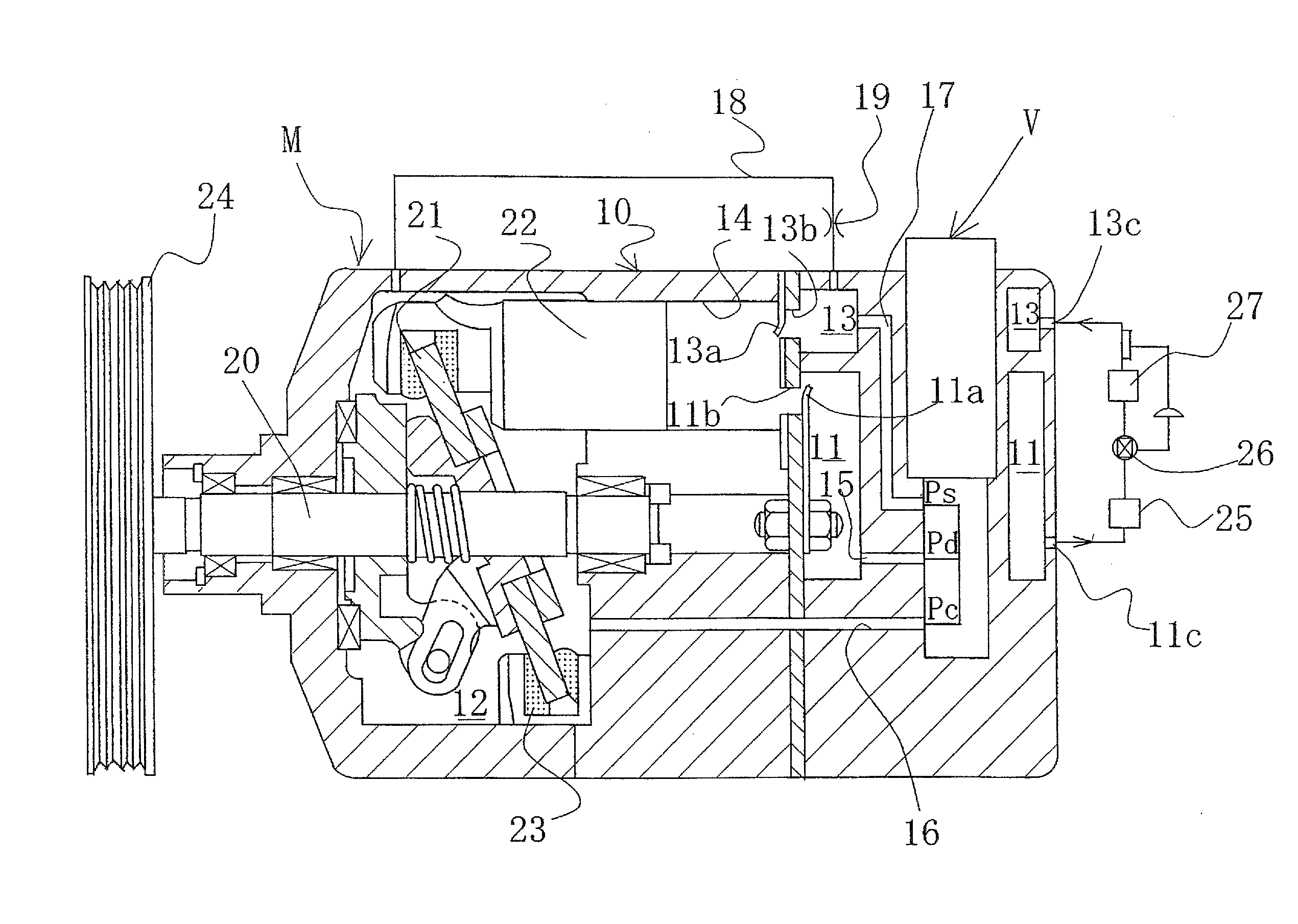
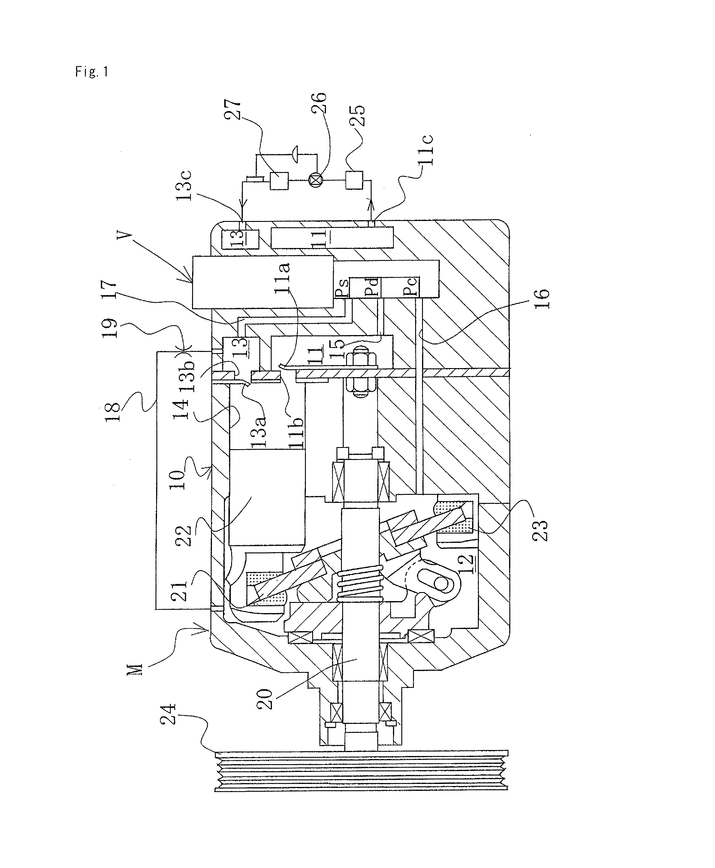
[0041]A variable-capacity swash plate compressor M is provided with a discharge chamber 11, a control chamber (also referred to as a crank chamber) 12, a suction chamber 13, a plurality of cylinders 14, a port 11b opened and closed by a discharge valve 11a and used to provide communication between the cylinders 14 and the discharge chamber 11, a port 13b opened and closed by a suction valve 13a and used to provide communication between the cylinders 14 and the suction chamber 13, a discharge port 11c and a suction port 13c connected to an external cooling circuit, a communication passage 15 used as a discharge-side pass...


PUM


Abstract

A capacity control valve for a variable-capacity compressor such as used in an air-conditioning system in a motor vehicle is provided, wherein foreign matter is prevented from being caught in the sliding parts and leakage on the sliding parts is prevented from occurring by configuring the capacity control valve so that there are no sliding parts between the valving element and the housing (valve body).

Description

TECHNICAL FIELD[0001]The present invention relates to a capacity control valve for variably controlling the capacity or pressure of a working fluid, and particularly relates to a capacity control valve for controlling, in accordance with the pressure load, the discharge rate of a variable-capacity compressor or the like used in the air-conditioning system of a motor vehicle or the like.BACKGROUND ART[0002]A variable-capacity swash plate compressor used in the air-conditioning system of a motor vehicle or the like is provided with a rotating shaft rotatably driven by the rotational force of the engine, a swash plate linked to the rotating shaft so that the angle of inclination can be varied, a compression piston linked to the swash plate, and the like. In the compressor, the stroke of the piston is varied by varying the angle of inclination of the swash plate to control the discharge rate of the coolant gas.[0003]The angle of inclination of the swash plate can be continuously varied ...

Claims


Application Information

Patent Timeline
Patent Type & Authority Applications(United States)
IPC IPC(8): F04B27/18F04B49/03
CPCF04B27/1804F04B2027/1845F04B2027/1831F04B2027/1827F04B2027/1854F04B27/08F04B27/14F04B49/00
Inventor FUKUDOME, KOHEICHO, RYOSUKEFUTAKUCHI, MASAYUKI
Owner EAGLE INDS
Why Eureka
Try Eureka