Apparatus and method for facilitating servicing of a liquid-cooled electronics rack

a technology for electronic racks and accessories, applied in electrical equipment construction details, transportation and packaging, lighting and heating equipment, etc., can solve the problems of difficult filling of pipes and cold plates, difficult to fill cooling pipes, and difficult to fill cooling plates, etc., to achieve effective utilization of floor space and density placement of server racks

Inactive Publication Date: 2012-08-09
INT BUSINESS MASCH CORP
View PDF12 Cites 6 Cited by
  • Summary
  • Abstract
  • Description
  • Claims
  • Application Information

AI Technical Summary

Benefits of technology

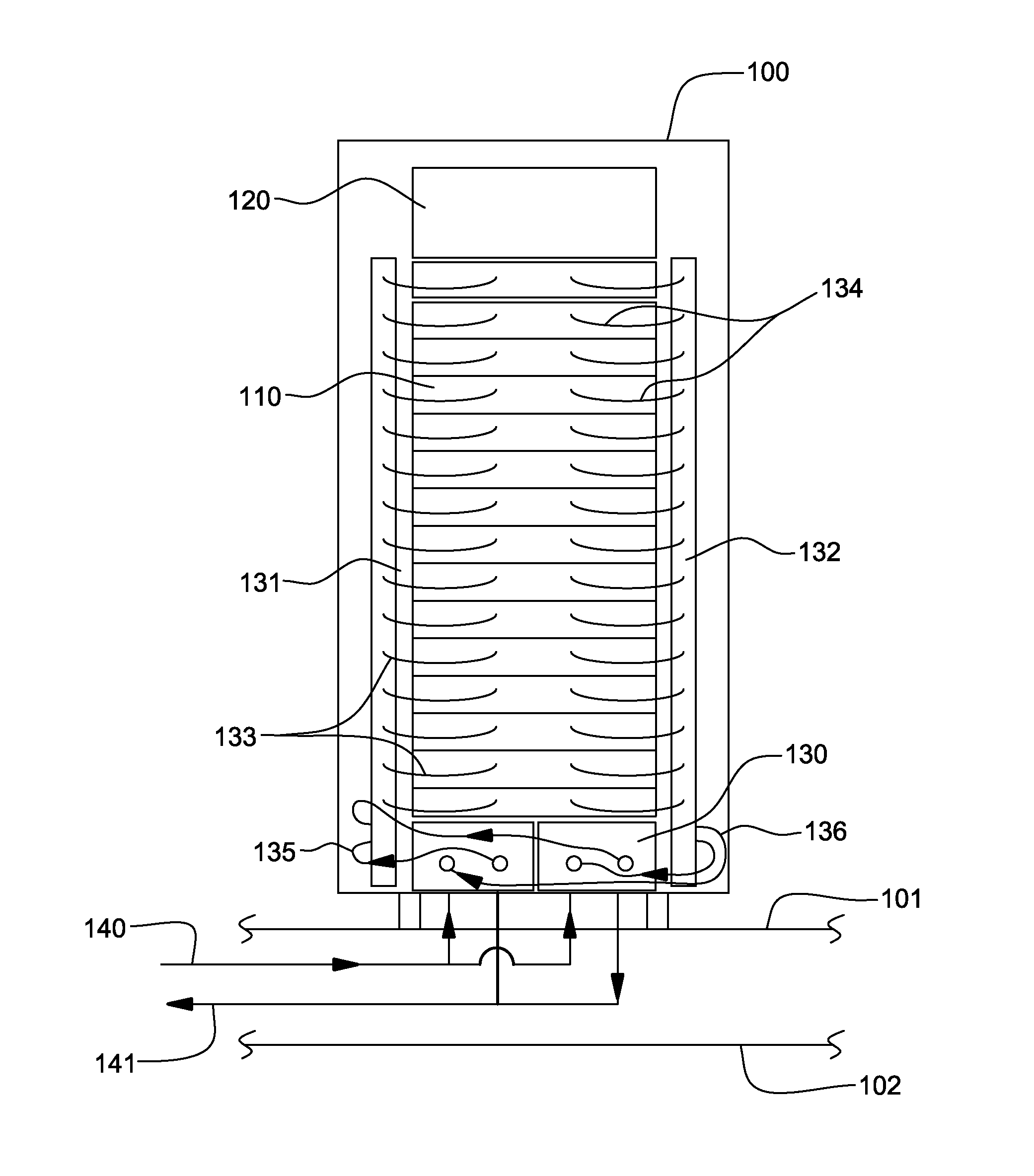
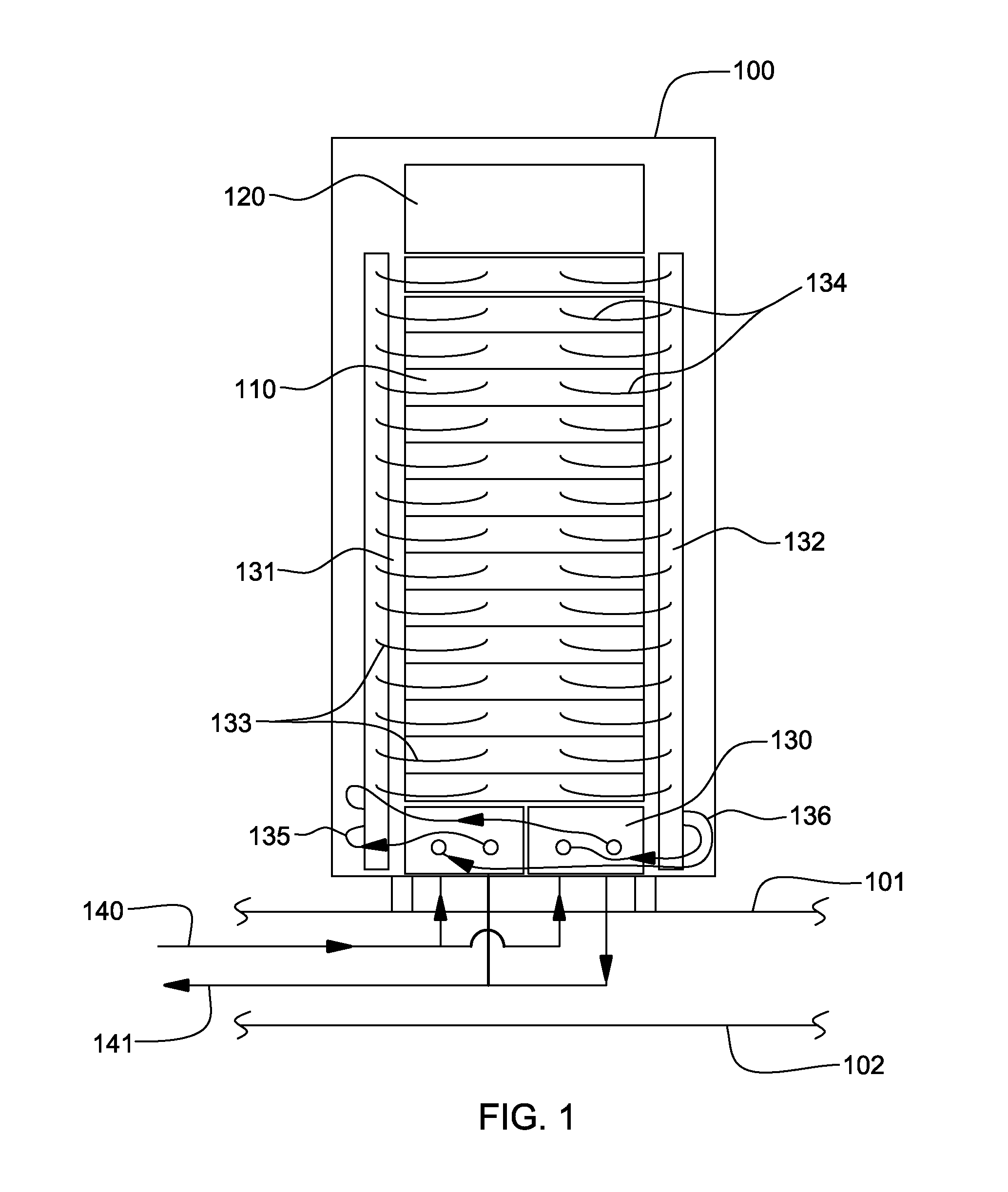
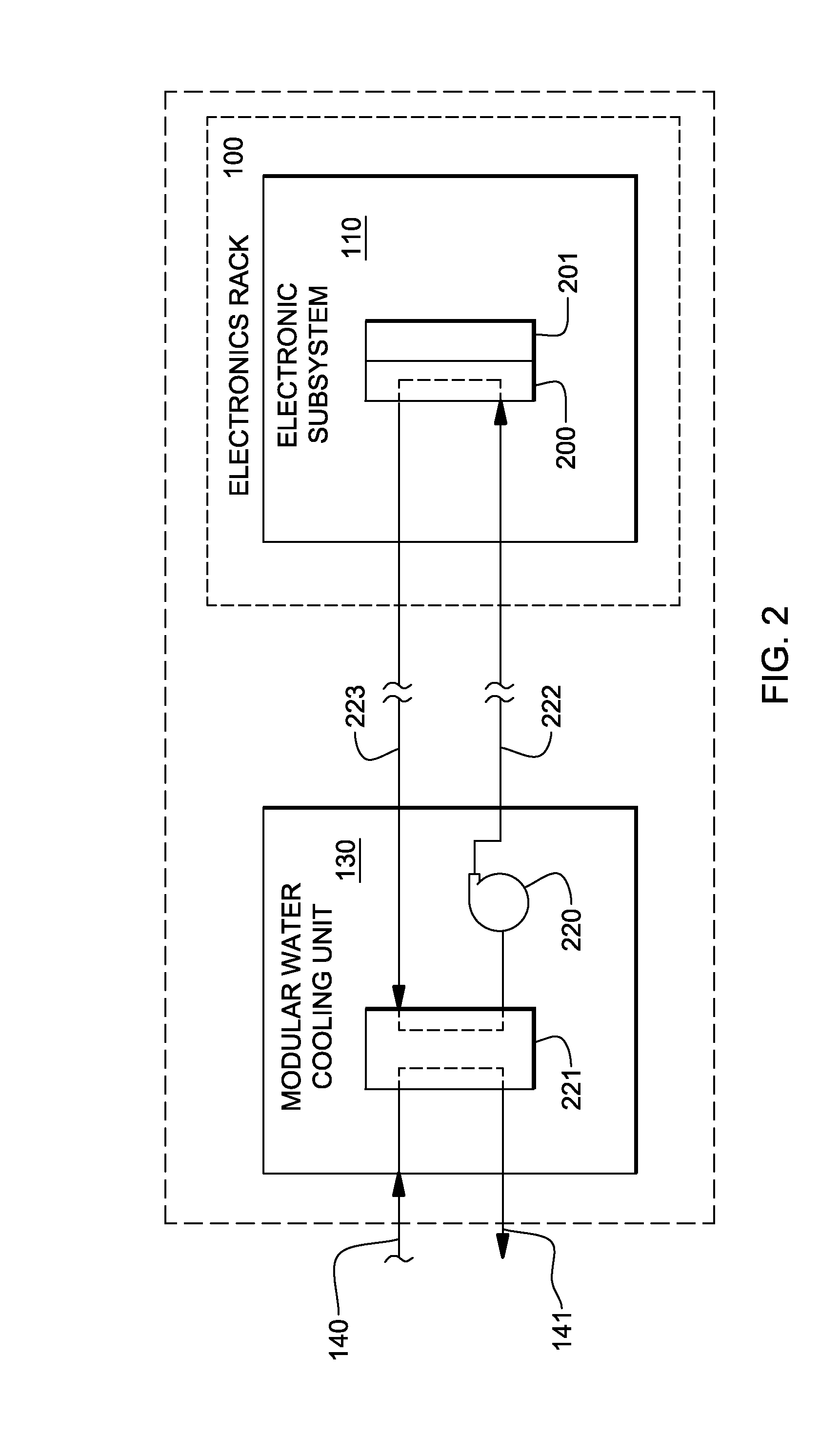
[0009]In one implementation, the large coolant distribution unit (CDU) of prior liquid-cooling approaches is eliminated, and replaced by one or more modular water cooling units (MWCUs) disposed within each server rack to be cooled. This results in a denser placement of server racks within the data center, and more effective utilization of floor space. At the same time, incorporation of the MWCUs at the bottom (for example) of a server rack makes filling and draining of coolant a more challenging problem. Earlier CDUs were much larger in size and contained a coolant reservoir / expansion tank that was large enough in size to contain enough liquid to fill all the pipes and cold plates in a system by filling the CDU expansion tank and pumping the coolant into the system piping and cold plates. In addition, ports in the top of the expansion tank were readily accessible to add liquid as required. Because of the location (e.g., at the bottom of an electronics rack) and small volume of the coolant reservoir within an MWCU, it is difficult to fill the pipes and cold plates of the cooling system by simply adding coolant to an opening in the top of the MWCU.
[0010]Thus, provided herein in one aspect, is an apparatus for facilitating servicing of a liquid-cooled electronics rack, and in particular, a liquid-cooled electronics rack employing one or more modular cooling units therein. The apparatus includes: a coolant tank; a coolant pump in fluid communication with the coolant tank for pumping coolant therefrom; multiple parallel-connected coolant supply lines coupling the coolant pump to a coolant supply port of the apparatus; and a coolant return port and a coolant return line coupled between the coolant return port and the coolant tank. Each coolant supply line of the multiple parallel-connected coolant supply lines includes a coolant control valve for selectively controlling flow of coolant therethrough pumped by the coolant pump from the coolant tank to the coolant supply port of the apparatus. At least one coolant supply line of the multiple parallel-connected coolant supply lines includes at least one filter, and one coolant supply line of the multiple parallel-connected coolant supply lines is a bypass coolant supply line with no filter. When operational, the apparatus facilitates filling of coolant into a cooling system of a liquid-cooled electronics rack by allowing for selective filtering of coolant inserted into the cooling system of the liquid-cooled electronics rack.

Problems solved by technology

At the same time, incorporation of the MWCUs at the bottom (for example) of a server rack makes filling and draining of coolant a more challenging problem.
Because of the location (e.g., at the bottom of an electronics rack) and small volume of the coolant reservoir within an MWCU, it is difficult to fill the pipes and cold plates of the cooling system by simply adding coolant to an opening in the top of the MWCU.

Method used


Image

  • Apparatus and method for facilitating servicing of a liquid-cooled electronics rack
  • Apparatus and method for facilitating servicing of a liquid-cooled electronics rack
  • Apparatus and method for facilitating servicing of a liquid-cooled electronics rack

Examples


Embodiment Construction

[0031]As used herein, the terms “electronics rack”, “rack-mounted electronic equipment”, and “rack unit” are used interchangeably, and unless otherwise specified include any housing, frame, rack, compartment, blade server system, etc., having one or more heat generating components of a computer system or electronics system, and may be, for example, a stand alone computer processor having high, mid or low end processing capability. In one embodiment, an electronics rack may comprise multiple electronics subsystems, each having one or more heat generating components disposed therein requiring cooling. “Electronics subsystem” refers to any sub-housing, blade, book, drawer, node, compartment, etc., having one or more heat generating electronic components disposed therein. Each electronics subsystem of an electronics rack may be movable or fixed relative to the electronics rack, with the rack-mounted electronics drawers of a multi-drawer rack unit and blades of a blade center system bein...


PUM

PropertyMeasurementUnit
timeaaaaaaaaaa
timeaaaaaaaaaa
flexibleaaaaaaaaaa

Abstract

An apparatus for facilitating servicing of a liquid-cooled electronics rack is provided. The apparatus includes a coolant tank, a coolant pump in fluid communication with the coolant tank, multiple parallel-connected coolant supply lines coupling the coolant pump to a coolant supply port of the apparatus, and a coolant return port and a coolant return line coupled between the coolant return port and the coolant tank. Each coolant supply line includes a coolant control valve for selectively controlling flow of coolant therethrough pumped by the coolant pump from the coolant tank. At least one coolant supply line includes at least one filter, and one coolant supply line is a bypass line with no filter. When operational, the apparatus facilitates filling of coolant into a cooling system of a liquid-cooled electronics rack by allowing for selective filtering of coolant inserted into the cooling system.

Description

CROSS-REFERENCE TO RELATED APPLICATIONS[0001]This application is a divisional of U.S. Ser. No. 11 / 942,221, entitled “Apparatus and Method for Facilitating Servicing of a Liquid-Cooled Electronics Rack,” filed Nov. 19, 2007, and published May 21, 2009, as U.S. Patent Publication No. 2009 / 0126910 A1, and which is hereby incorporated herein by reference in its entirety. This application also contains subject matter which is related to the subject matter of the following applications, each of which is assigned to the same assignee as this application and each of which is hereby incorporated herein by reference in its entirety:[0002]“Docking Station with Closed Loop Airflow Path for Facilitating Cooling of an Electronics Rack”, by Campbell et al., U.S. patent application Ser. No. 11 / 862,328, filed Sep. 27, 2007, and published Apr. 2, 2009, as U.S. Patent Publication No. 2009 / 0086432 A1;[0003]“Docking Station with Hybrid Air and Liquid Cooling of an Electronics Rack”, by Campbell et al., ...

Claims


Application Information

Patent Timeline
Patent Type & Authority Applications(United States)
IPC IPC(8): F28F27/00
CPCH05K7/20781Y10T29/4935Y10T29/49002Y10T29/49826Y10T29/49352
Inventor CAMPBELL, LEVI A.CHU, RICHARD C.ELLSWORTH, JR., MICHAEL J.IYENGAR, MADHUSUDAN K.SIMONS, ROBERT E.SINGH, PRABJIT
Owner INT BUSINESS MASCH CORP
Why Eureka
Try Eureka