

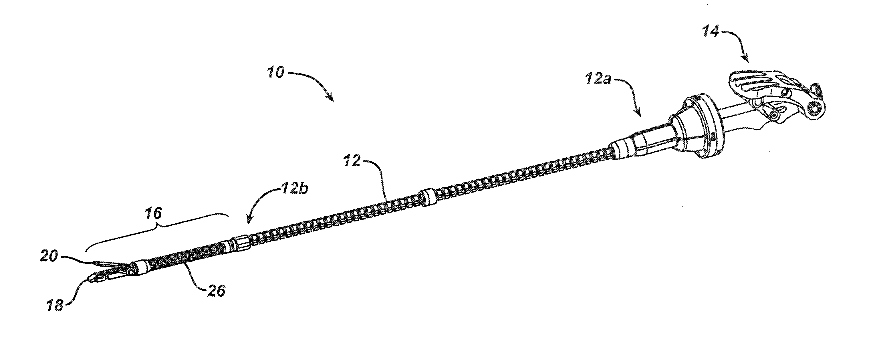
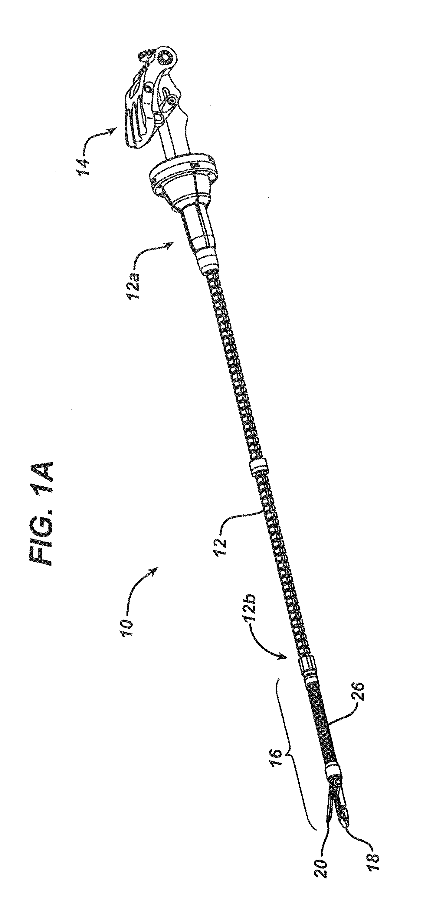
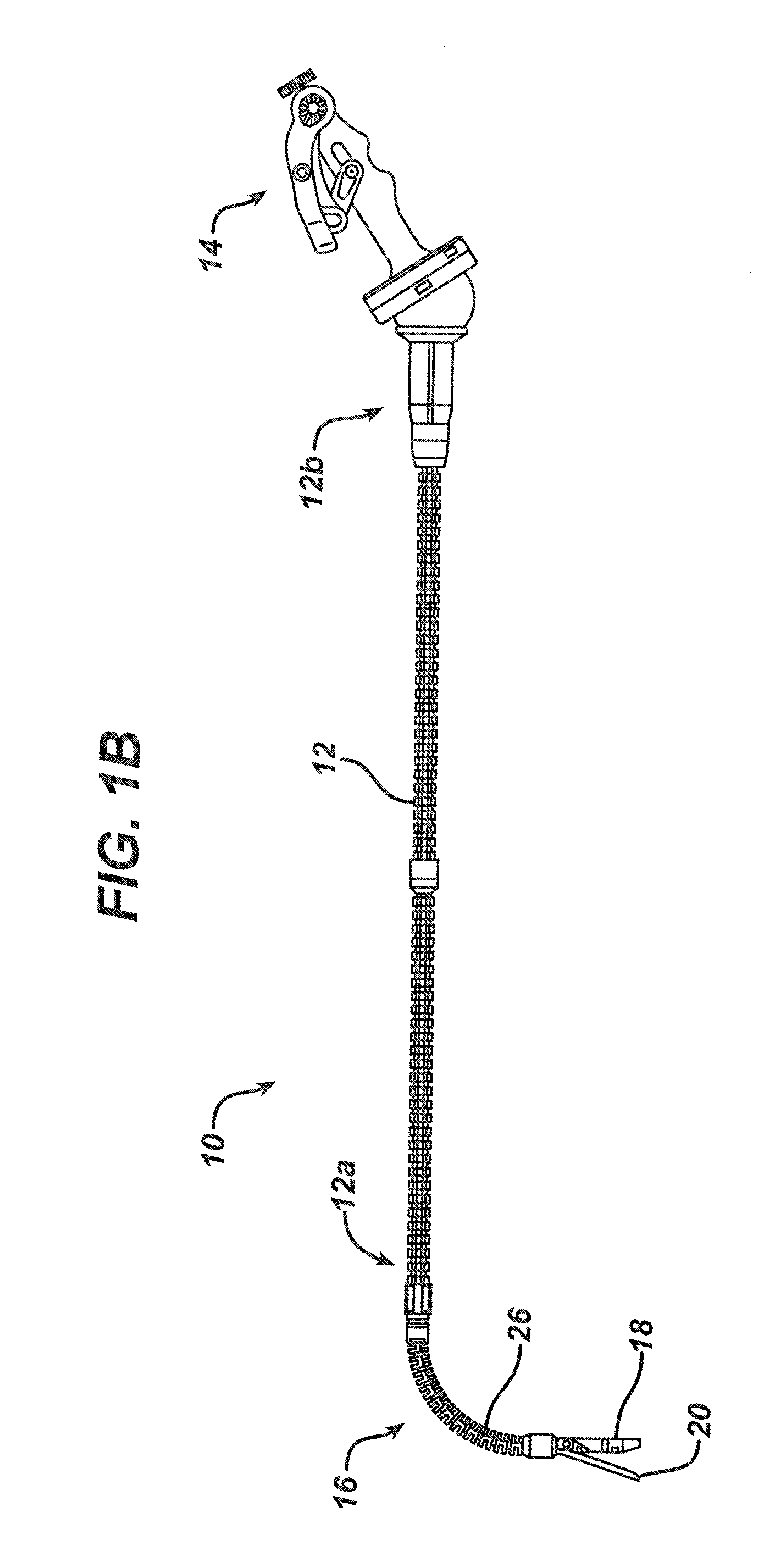
Robotically-controlled surgical instrument with selectively articulatable end effector
a surgical instrument and end effector technology, applied in the direction of surgical staples, surgical forceps, applications, etc., can solve the problems of inability to suitably achieve user-feedback effects, complicated integration of controls for articulating and actuating the working end of the endoscopic device, and interfere with the flexibility of the sha
- Summary
- Abstract
- Description
- Claims
- Application Information
AI Technical Summary
Benefits of technology
Problems solved by technology
Method used
Image

Examples
Embodiment Construction
[0161]Applicant of the present application also owns the following patent applications that were filed on May 27, 2011 and which are each herein incorporated by reference in their respective entireties:
[0162]U.S. patent application Ser. No. 13 / 118,259, entitled “Surgical Instrument With Wireless Communication Between a Control Unit of a Robotic System and Remote Sensor”;
[0163]U.S. patent application Ser. No. 13 / 118,210, entitled “Robotically-Controlled Disposable Motor Driven Loading Unit”;
[0164]U.S. patent application Ser. No. 13 / 118,253, entitled “Robotically-Controlled Motorized Surgical Instrument”;
[0165]U.S. patent application Ser. No. 13 / 118,278, entitled “Robotically-Controlled Surgical Stapling Devices That Produce Formed Staples Having Different Lengths”;
[0166]U.S. patent application Ser. No. 13 / 118,190, entitled “Robotically-Controlled Motorized Cutting and Fastening Instrument”;
[0167]U.S. patent application Ser. No. 13 / 118,223, entitled “Robotically-Controlled Shaft Based...
PUM
| Property | Measurement | Unit |
|---|---|---|
| length | aaaaa | aaaaa |
| circumference | aaaaa | aaaaa |
| circumference | aaaaa | aaaaa |
Abstract
Description
Claims
Application Information