Retaining Device and Method of Using the Same

a technology of retaining device and end portion, which is applied in the direction of custody suspension device, surgical instrument support, furniture parts, etc., can solve the problems of difficult management of the end portion of the trailer, and achieve the effect of simple and secure loading and easy operation

Active Publication Date: 2012-08-09
TAYLOR KEVIN D
View PDF9 Cites 16 Cited by
  • Summary
  • Abstract
  • Description
  • Claims
  • Application Information

AI Technical Summary

Benefits of technology

[0009]An advantage of the invention is to provide an apparatus to securely retain a medical wire to a medical surface while providing ease of loading and removal of the medical wire from the apparatus.
[0010]Yet another advantage of the invention is to provide a simple and secure mechanism to attach an apparatus to a surface.
[0011]Still yet another advantage of the invention is to provide a retention device that allows a guide and catheter exchanges without having to remove the guidewire or catheter from the retention device. Additional features and advantages of the invention will be set forth in the description which follows, and in part will be apparent from the description, or may be learned by practice of the invention. The objectives and other advantages of the invention will be realized and attained by the structure particularly pointed out in the written description and claims hereof as well as the appended drawings.
[0012]To achieve these and other advantages and in accordance with the purpose of the present invention, as embodied and broadly described, an aspect of the invention is directed towards a retaining device for securing a medical apparatus during a medical procedure. The retaining device includes a base portion and a holding portion arranged at a predetermined angle from the base portion. The holding portion includes a peripheral edge including a slot extending from the peripheral edge defining a loading channel and communicating with an internal holding area. The internal holding area is dimensioned to accept the medical apparatus via the loading channel. An attachment mechanism is configured to secure the base portion to a supporting surface, e.g., cloth, medical gown, surgical drape, table or other substrate.
[0013]Another aspect of the invention is directed towards a method of using a retaining device to secure a medical apparatus to a predetermined location. The method includes attaching a retaining device to a substrate. The retaining device includes a loading channel and a holding area. Opening the loading channel of the retaining device and arranging a portion of the medical apparatus through the loading channel into a holding area of the retaining device.
[0014]Yet another embodiment of the invention is directed towards a medical kit and instructions for use. The medical kit includes a retaining device according to any embodiment of the invention.

Problems solved by technology

This trailing end portion can be difficult to manage and requires special attention from the medical staff to ensure it does not become contaminated, tangled or confused with other wires in the procedural area.

Method used


Image

  • Retaining Device and Method of Using the Same
  • Retaining Device and Method of Using the Same
  • Retaining Device and Method of Using the Same

Examples


example 1

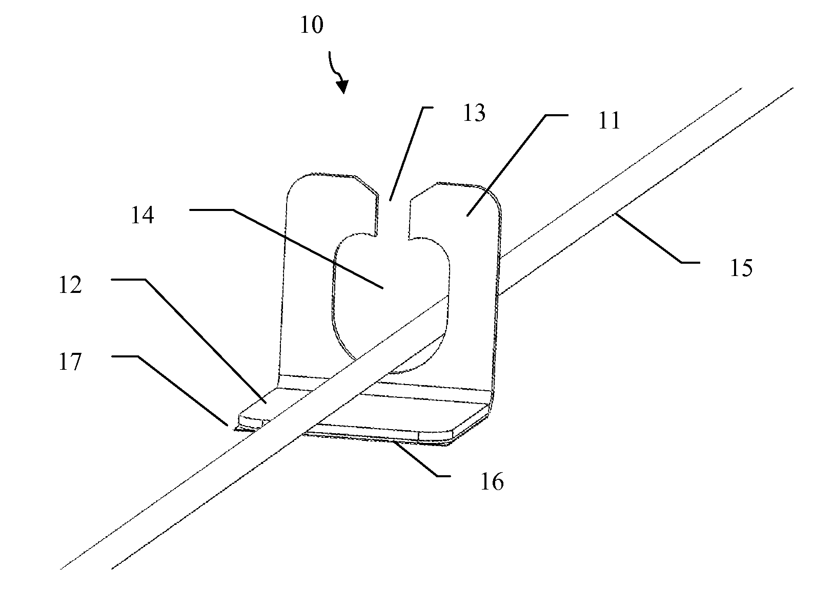
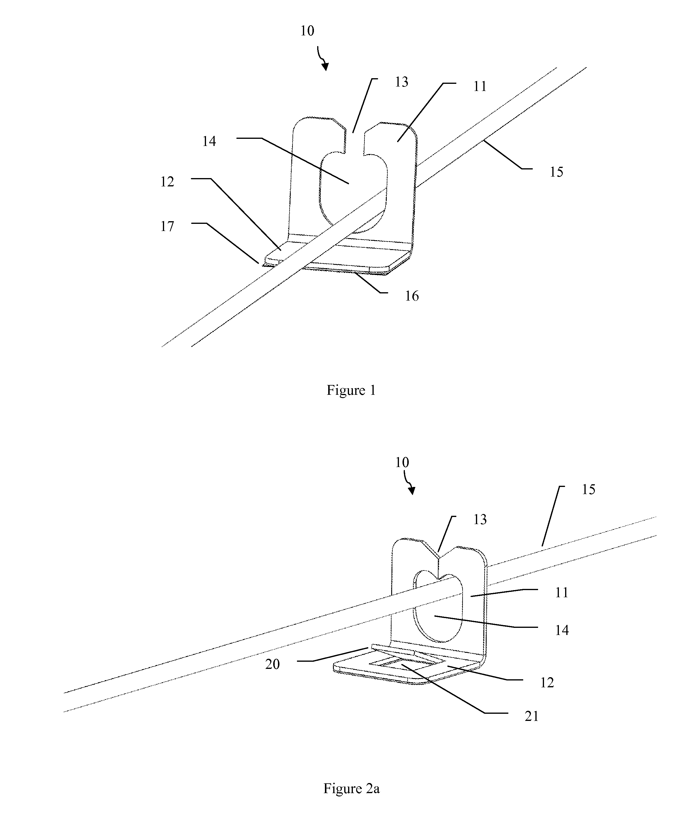
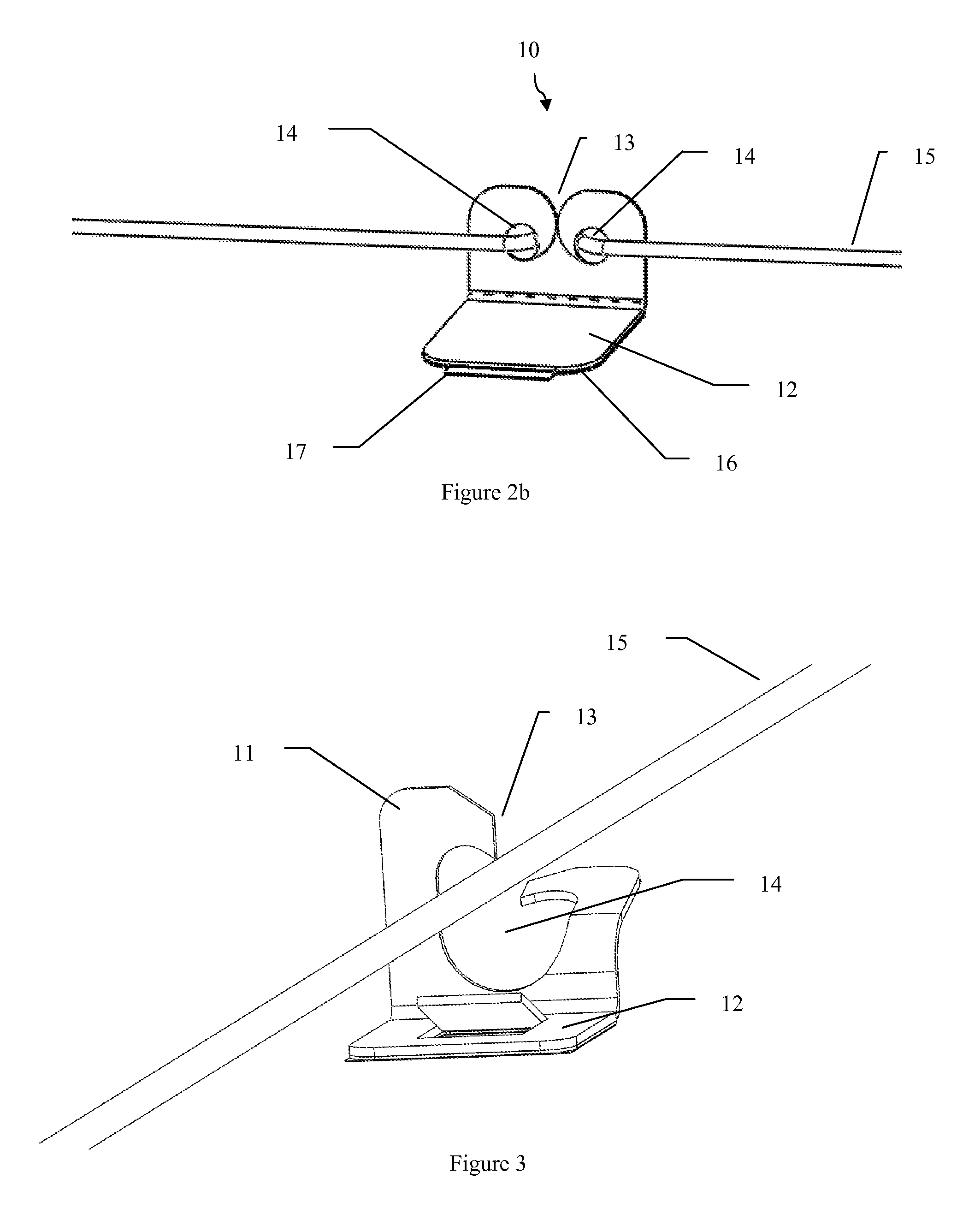
[0052]In this example, a retaining device similar to the device shown in FIG. 2B was fabricated. A rectangular polypropylene sheet being about 1.25 inches by 2 inches and about 0.03 thick was utilized. The corners of this sheet were radiused to about 0.25 inches with cutting shears. Two holes being about 0.25 inches in diameter were punched in the holder portion using a leather punch. The center of each hole was spaced about 0.50 inches from each other and extended from the top edge about 0.38 inches and the side edge at about 0.38 inches. Each side of the loading channel was cut to include about a 0.25 inch radius shear cut extending from the top edge and communicating with the bottom of each hole. In addition, a linear perforated line was punched across the part, parallel to and about 0.75 inches from the top edge using a perforated leather punch to form a living hinge.

[0053]A pressure sensitive adhesive with protective liner was cut to match the base portion and adhered to the bo...


PUM

PropertyMeasurementUnit
angleaaaaaaaaaa
angleaaaaaaaaaa
thicknessaaaaaaaaaa

Abstract

A retaining device configured for retaining at least one medical device adjacent to a supporting surface. The retaining device includes a plate shaped holding portion defining a peripheral edge, a slot extending from the peripheral edge defining a loading channel, and communicating with an internal holding area. The internal holding area is dimensioned to accept the largest medical device the retaining device is configured to be used with. An attachment mechanism is connected to the holding portion to secure the retaining device to a supporting surface. A section of medical device may be inserted into and along the loading channel to enter the holding area and be retained within.

Description

[0001]This application claims the benefit of U.S. Provisional Patent Application No. 61 / 440,272, filed on Feb. 7, 2011, which is hereby incorporated by reference for all purposes as if fully set forth herein.BACKGROUND OF THE INVENTION[0002]1. Field of the Invention[0003]The present invention relates to retaining devices and, more specifically, retaining devices for securing medical wires, catheters, guidewires, electrical lines, cables, tubing and other elongated members during medical procedures.[0004]2. Discussion of the Related Art[0005]Guidewires and catheters are used in a variety of different medical procedures such as, angiographic, endovascular, or surgical procedures. Guidewires are typically used to position catheters in a body lumen, for example arteries, veins or natural orifices within a mammal. The leading end portion of the guidewire is typically introduced into the body through an incision or natural orifice and then advanced to the treatment area. A catheter can be...

Claims


Application Information

Patent Timeline
Patent Type & Authority Applications(United States)
IPC IPC(8): F16L3/08F16M13/00F16M13/02B23P17/04
CPCF16G11/00F16G11/02F16G11/146A61B17/085Y10T29/49826A61B19/26F16L3/1218A61B2017/22038A61M5/1418A61B19/10A61B46/23A61B90/50
Inventor TAYLOR, KEVIN D.
Owner TAYLOR KEVIN D
Why Eureka
Try Eureka