
Integrated circuit having power gating function and semiconductor device including the same

a technology of integrated circuits and functions, applied in the field of integrated circuits, can solve problems such as data loss of function blocks, and achieve the effect of low power consumption and reduced leakage current in logic circuits

Inactive Publication Date: 2012-08-09
SAMSUNG ELECTRONICS CO LTD
View PDF7 Cites 28 Cited by
  • Summary
  • Abstract
  • Description
  • Claims
  • Application Information

AI Technical Summary

Benefits of technology

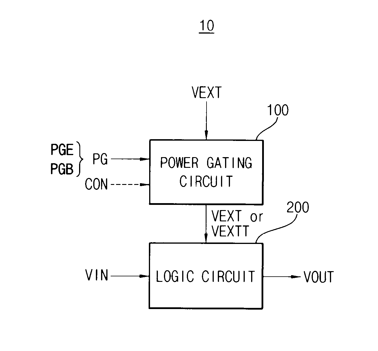
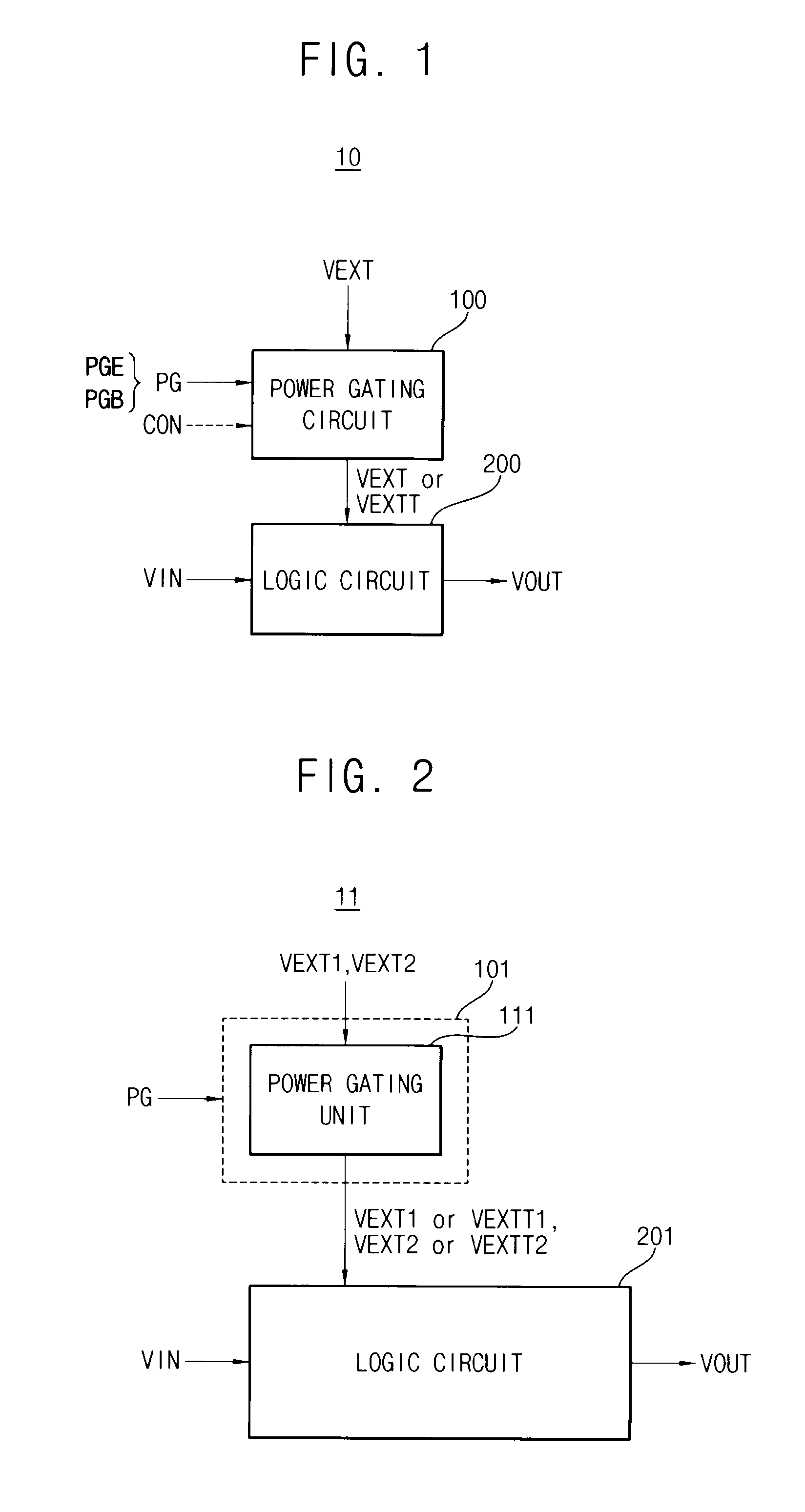
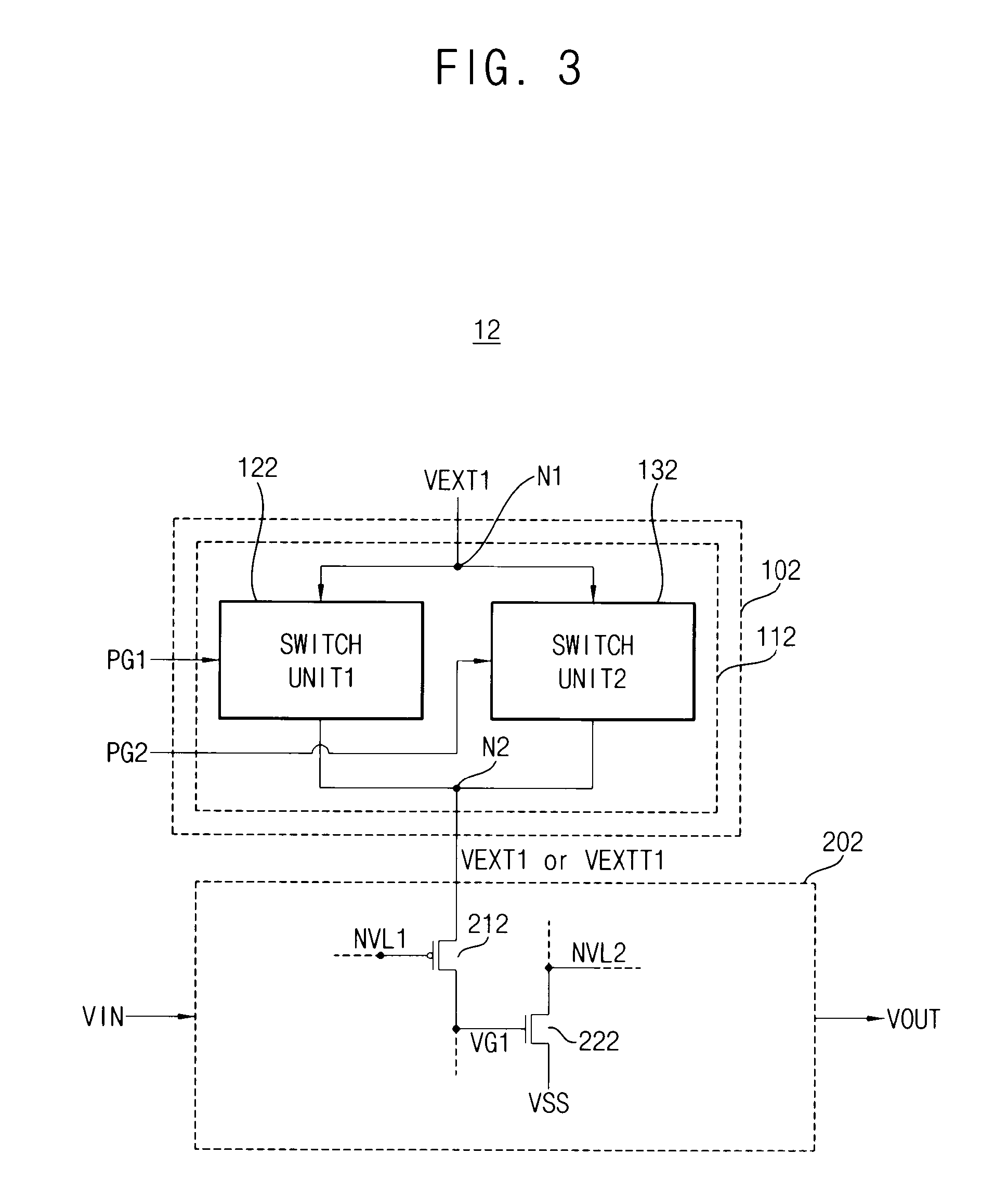
The invention provides an integrated circuit that can reduce power consumption in a stand-by mode by using a power gating circuit. The circuit includes a logic circuit and a power gating circuit that can apply a lower power supply voltage to the logic circuit in the stand-by mode without needing an additional device. The power gating circuit can also partially apply a higher power supply voltage to the logic circuit in the stand-by mode. This can help to retain data in the stand-by mode without needing an additional device. The power gating circuit can include a first power gating unit and a second power gating unit that apply different power supply voltages to the logic circuit based on a power gating signal. The logic circuit can include an active region that is activated in the stand-by mode to maintain the voltage level of the output signal. The power gating circuit can also include a first switch unit and a second switch unit that provide the different power supply voltages to the logic circuit based on the power gating signal. The logic circuit can also include an inactive region that is deactivated in the stand-by mode. Overall, the invention provides a solution to reduce power consumption in a stand-by mode without needing an additional device.

Problems solved by technology

However, when power is blocked to the function blocks during the stand-by mode, data within the function blocks may be lost.

Method used


Image

  • Integrated circuit having power gating function and semiconductor device including the same
  • Integrated circuit having power gating function and semiconductor device including the same
  • Integrated circuit having power gating function and semiconductor device including the same

Examples


Embodiment Construction

[0042]Various example embodiments of the inventive concept will be described more fully with reference to the accompanying drawings. The inventive concepts may, however, be embodied in many different forms and should not be construed as limited to the embodiments set forth herein. Rather, these embodiments are provided so that this disclosure will be thorough and complete, and will fully convey the scope of the inventive concept to those skilled in the art. Like reference numerals refer to like elements throughout this application.

[0043]It will be understood that, although the terms first, second, etc. may be used herein to describe various elements, these elements should not be limited by these terms. These terms are used to distinguish one element from another. For example, a first element could be termed a second element, and, similarly, a second element could be termed a first element, without departing from the scope of the inventive concept. As used herein, the term “and / or” i...


PUM


Abstract

An integrated circuit includes a logic circuit and a power gating circuit. The logic circuit generates an output signal based on an input signal and a first power supply voltage in a normal operation mode, and maintains a voltage level of the output signal as a stand-by logic level based on a second power supply voltage in a stand-by mode. A magnitude of the second power supply voltage is smaller than a magnitude of the first power supply voltage. The power gating circuit entirely applies the first power supply voltage to the logic circuit based on a power gating signal in the normal operation mode, and partially applies the second power supply voltage to the logic circuit based on the power gating signal in the stand-by mode.

Description

CROSS-REFERENCE TO RELATED APPLICATION[0001]A claim of priority under 35 USC §119 has been made to Korean Patent Application No. 2011-0010983, filed on Feb. 8, 2011, the entirety of which is incorporated herein by reference in its entirety.BACKGROUND OF THE INVENTION[0002]The inventive concepts herein relate to an integrated circuit, and more particularly, relate to an integrated circuit having a power gating function and a semiconductor device including the integrated circuit.[0003]Semiconductor devices are typically required to be of small size and light weight, whereby the number of required function blocks within the semiconductor devices has increased. Generally, since semiconductor devices are required to operate with limited power (e.g., using an embedded battery), power consumption of the semiconductor device should be reduced by adopting a stand-by mode. To reduce power consumption, the semiconductor device may include a power gating circuit that prevents power from being p...

Claims


Application Information

Patent Timeline
Patent Type & Authority Applications(United States)
IPC IPC(8): G05F3/02
CPCH03K19/0016G11C5/14
Inventor KIM, JUNG-SIK
Owner SAMSUNG ELECTRONICS CO LTD
Learn More