Stack type battery and method of manufacturing the same

a technology of stack type and battery case, which is applied in the direction of sustainable manufacturing/processing, flat cell grouping, secondary cell details, etc., can solve the problems of affecting the service life of the battery case, so as to prevent the misalignment of the current collector terminal and the effect of creases in the battery cas

Inactive Publication Date: 2012-08-09
SANYO ELECTRIC CO LTD
View PDF6 Cites 57 Cited by
  • Summary
  • Abstract
  • Description
  • Claims
  • Application Information

AI Technical Summary

Benefits of technology

[0026]The present invention makes it possible to effectively prevent misalignment o...

Problems solved by technology

In this process, a problem arises that sharp edges or burrs, for example, of the metal in the positive and negative electrode current collector leads or in the welded portion between the positive and negative electrode current collector leads and the positive and negative electrode current collector terminals are pressed against and brought into contact with the laminate film of the ...

Method used


Image

  • Stack type battery and method of manufacturing the same
  • Stack type battery and method of manufacturing the same
  • Stack type battery and method of manufacturing the same

Examples


first embodiment

Preparation of Positive Electrode

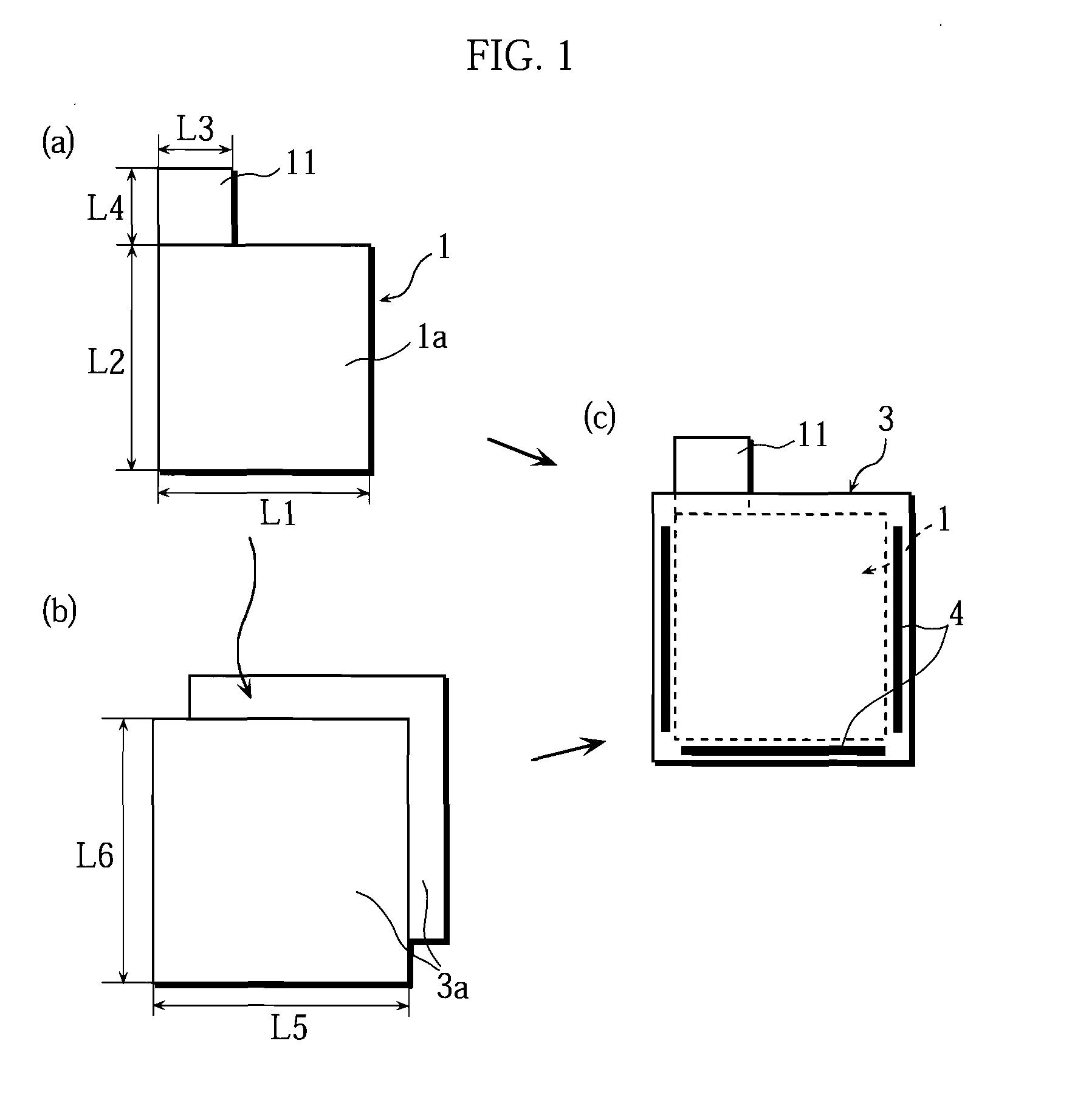
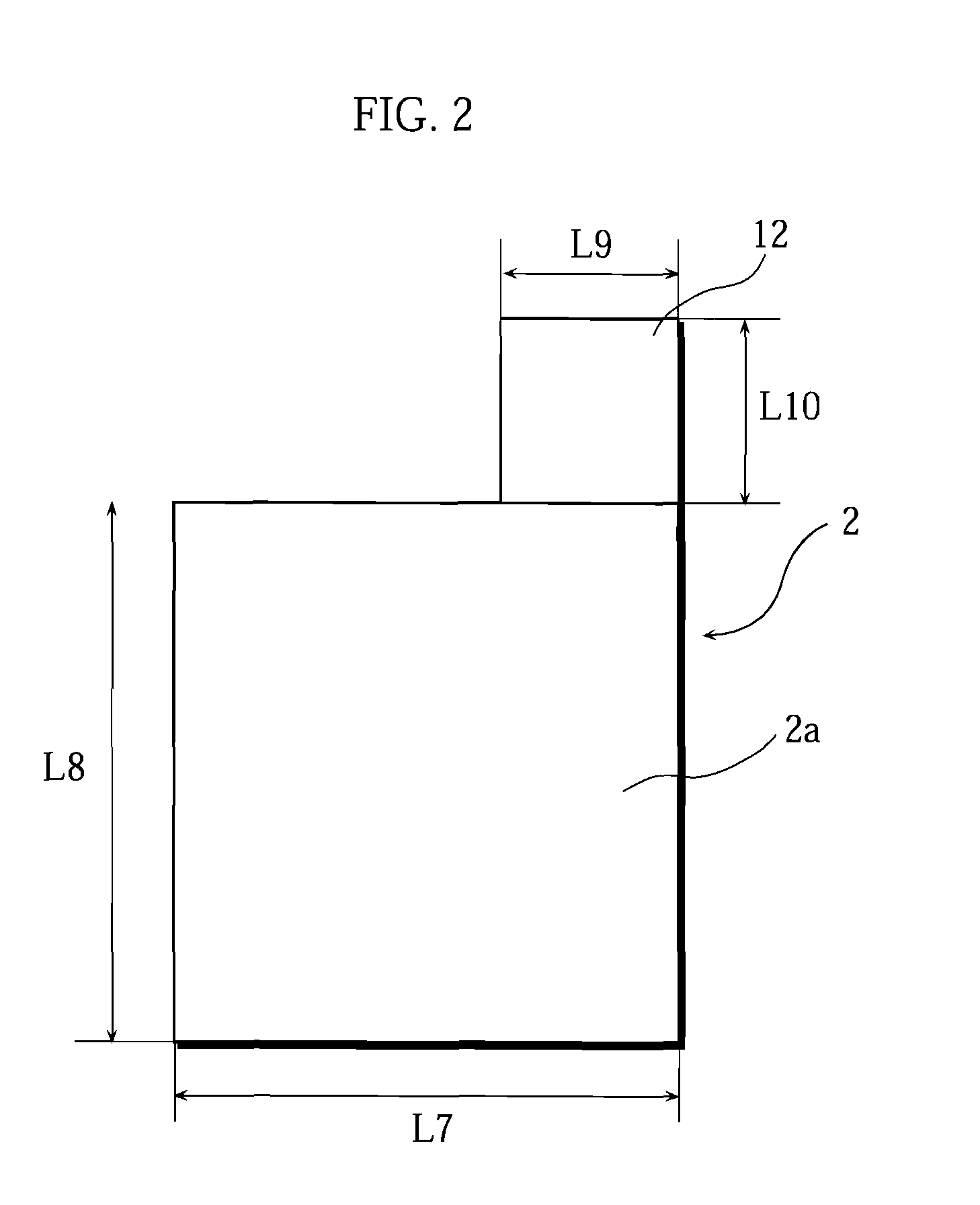
[0098]90 mass % of LiCoO2 as a positive electrode active material, 5 mass % of carbon black as a conductive agent, and 5 mass % of polyvinylidene fluoride as a binder agent were mixed with an N-methyl-2-pyrrolidone (NMP) solution as a solvent to prepare a positive electrode mixture slurry. The resultant positive electrode slurry was applied onto both sides of an aluminum foil (thickness: 15 μm) serving as a positive electrode current collector. Thereafter, the material was heated to remove the solvent and compressed with rollers to a thickness of 0.1 mm. Subsequently, as illustrated in FIG. 1(a), it was cut into pieces each having a width L1 of 85 mm and a height L2 of 85 mm, to prepare positive electrode plates 1 each having a positive electrode active material layer 1a on each side. At this point, in each of the positive electrode plates 1, an active material-uncoated portion having a width L3=30 mm and a height L4=20 mm was allowed to protrude out...

second embodiment

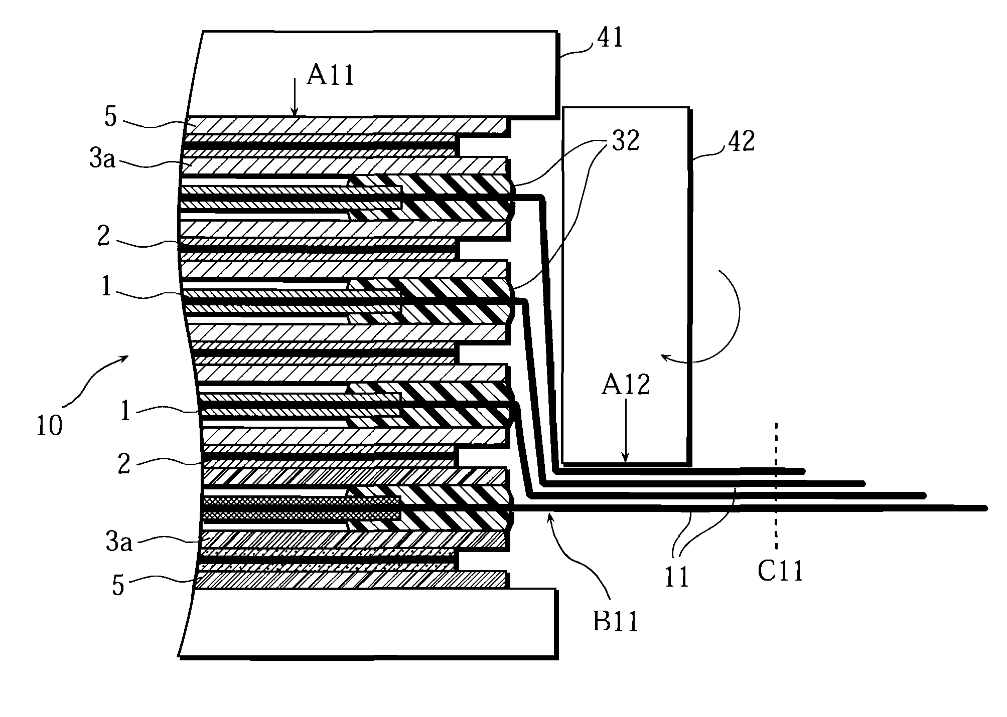
[0119]FIGS. 14 through 16 are schematic partial cross-sectional views illustrating various types of stack type batteries according to other embodiments of the present invention. FIGS. 14 through 16 are schematic partial cross-sectional views each showing a part corresponding to that shown in FIG. 13. As is clear from FIGS. 14 through 16, many of the parts and components of various types of stack type batteries according to these other embodiments are basically the same as the parts and components in the first embodiment. For this reason, in the following description and FIGS. 14 through 16, parts and components that are identical or similar to those described in the first embodiment above are denoted by like reference numerals, and the descriptions thereof will not be given except when necessary.

1>

[0120]In a battery A2 shown in FIG. 14, the fastening tape 46 as the fastening means in the first embodiment is not provided. Instead, an inner insulating layer 47N made of a 35 μm-thick i...


PUM

PropertyMeasurementUnit
Thicknessaaaaaaaaaa
Thicknessaaaaaaaaaa

Abstract

A stack type battery has a stacked electrode assembly (10) having a plurality of positive electrode plates having respective positive electrode current collector leads (11) protruding therefrom, a plurality of negative electrode plates (2) having respective negative electrode current collector leads protruding therefrom, and separators (3a) interposed between the positive electrode plates (1) and the negative electrode plates (2). The stacked positive electrode current collector leads (11) and the stacked negative electrode current collector leads are bundled at one stacking direction-wise side of the stacked electrode assembly (10), and a portion of the bundled leads is bent toward the other stacking direction-wise side. The positive electrode current collector leads (11) or the negative electrode current collector leads are provided with a fastening tape (46) for retaining a portion of the bundled leads in a folded shape so as to be pulled toward the positive and negative electrode plates (1, 2).

Description

BACKGROUND OF THE INVENTION[0001]1. Field of the Invention[0002]The present invention relates to a stack type battery and a method of manufacturing the battery.[0003]2. Description of Related Art[0004]In recent years, batteries have been used for not only the power source of mobile information terminal devices such as mobile-phones, notebook computers, and PDAs but also for such applications as robots, electric vehicles, and backup power sources. This has led to a demand for higher capacity batteries. Because of their high energy density and high capacity, lithium-ion batteries are widely used as the power sources for such applications as described above.[0005]The battery configurations of the lithium-ion batteries are broadly grouped into two types: one is a spirally-wound type lithium-ion battery, in which a spirally wound electrode assembly is enclosed in a battery case, and the other is a stack type lithium-ion battery (stack-type prismatic lithium ion battery), in which a stack...

Claims


Application Information

Patent Timeline
IPC IPC(8): H01M10/02H01M4/26H01M10/04H01M50/528H01M50/533H01M50/54
CPCH01M2/22H01M2/266H01M10/0413H01M10/0436H01M10/0468Y10T29/4911H01M10/0583H01M10/0585Y02E60/122Y10T29/49108H01M10/052Y02E60/10H01M50/528H01M50/54Y02P70/50H01M50/533
Inventor SHINYASHIKI, YOSHITAKAFUJIWARA, MASAYUKI
Owner SANYO ELECTRIC CO LTD
Why Eureka
Try Eureka