Power detection device and method of driving the same

a technology of power detection and detection device, which is applied in the direction of transmission monitoring, modulation, electrical equipment, etc., can solve the problems of power consumption increase, degradation of production yield, and difficulty in manufacturing components with characteristics sufficient to mutually cancel out temperature coefficients, and achieve high precision

Inactive Publication Date: 2012-08-09
ROHM CO LTD
View PDF3 Cites 9 Cited by
  • Summary
  • Abstract
  • Description
  • Claims
  • Application Information

AI Technical Summary

Benefits of technology

[0009]The present disclosure provides some embodiments of a power detection device capable of executing temperature compensation of

Problems solved by technology

However, the Zener diode and the detection diode have different structures manufactured in different processes, and thus, it is often difficult to manufacture those components with characteristics sufficient to mutually cancel out the temperature coefficients of the Zener diode and the detection diode.
This makes it difficult to produce a circuit with an appropriate combination of the above mentioned components, which leads to a degradation of a production yield.
Further, this causes the power consumption to increase because of the amount of a current

Method used


Image

  • Power detection device and method of driving the same
  • Power detection device and method of driving the same
  • Power detection device and method of driving the same

Examples


Embodiment Construction

[0018]Reference will now be made in detail to various embodiments, examples of which are illustrated in the accompanying drawings. In the following detailed description, numerous specific details are set forth in order to provide a thorough understanding of the present invention(s). However, it will be apparent to one of ordinary skill in the art that the present invention(s) may be practiced without these specific details. In other instances, well-known methods, procedures, systems, and components have not been described in detail so as not to unnecessarily obscure aspects of the various embodiments. In a following description of drawings, the same or like reference numerals are used for the same or like parts. Drawings regarding structures are schematic and parts having mutually different dimension relations and rates are included in drawings.

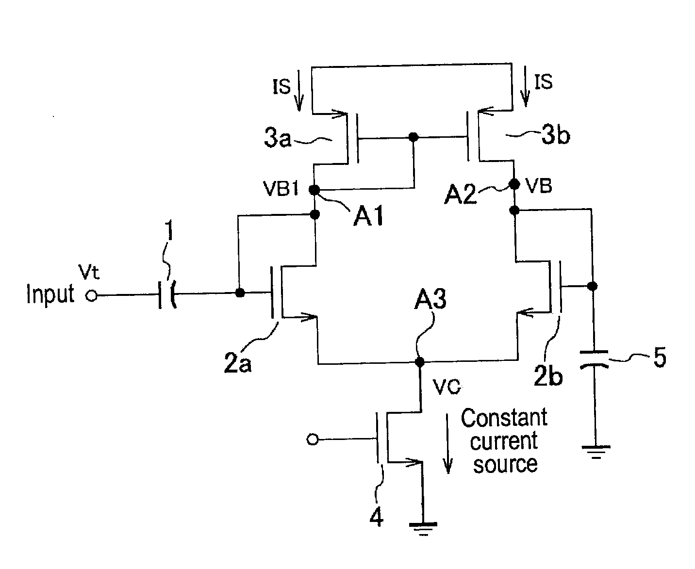
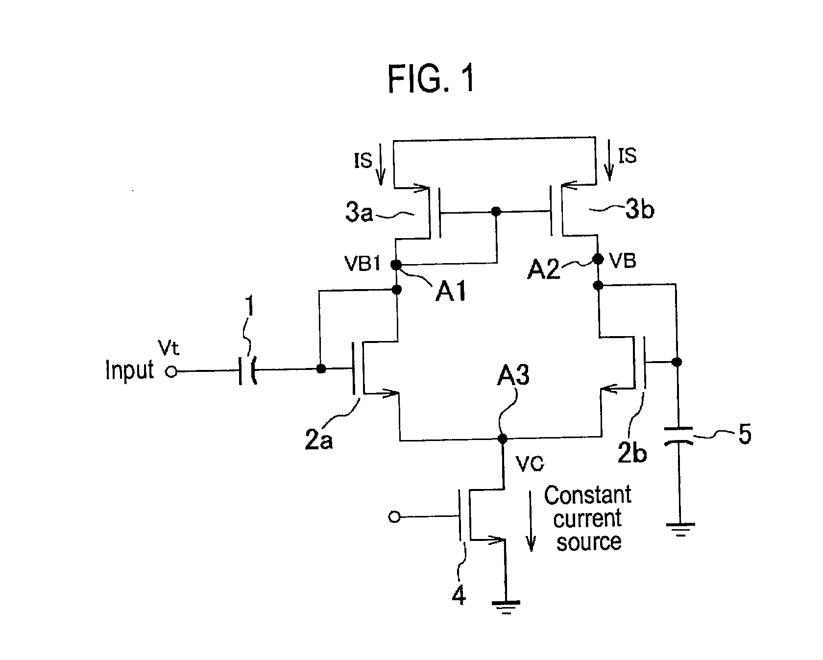
[0019]First, a power detection circuit may be configured as shown in FIG. 1. FIG. 1 is a circuit diagram illustrating a basic circuit config...


PUM


Abstract

A power detection device includes first and second power detection circuits configured to output a first and second detection signals, respectively, each including a half-wave rectifier circuit having a transistor, and connected to an RF input terminal, a ripple filter having a transistor and a capacitor, and configured to filter ripples of a rectified signal from the half-wave rectifier circuit, a transmission circuit having a pair of transistors, and connected to the half-wave rectifier circuit and the ripple filter to transfer the rectified signal to the ripple filter, and a constant current source having a transistor to supply a current to the half-wave rectifier circuit, the ripple filter, and the transmission circuit, and a subtraction circuit configured to receive the first and second detection signals and to calculate a difference between the two signals.

Description

CROSS-REFERENCE TO RELATED APPLICATION[0001]This application is based upon and claims the benefit of priority from Japan Patent Application No. 2011-21416, filed on Feb. 3, 2011, the entire contents of which are incorporated herein by reference.TECHNICAL FIELD [0002]The present disclosure relates to a power detection device and a method of driving the power device, which is used for wireless devices, detects transmission power, and control an output voltage.BACKGROUND [0003]A wireless device is required to maintain a good communication quality, and power of its output signal should be controlled such that it does not interfere with another wireless device. In particular, a mobile wireless device is required to control power with a high precision in comparison to a fixed wireless device because a distance between mobile devices and their antenna orientations thereof are frequently changed.[0004]Due to temperature characteristics of a semiconductor used in a power detector, the amplit...

Claims


Application Information

Patent Timeline
IPC IPC(8): H04B17/00
CPCH04B2001/0416G01R21/10
Inventor MIMINO, YUTAKA
Owner ROHM CO LTD
Why Eureka
Try Eureka