
System and method for mitigating an electric unbalance of a three-phase current at a point of common coupling between a wind farm and a power grid

a technology of three-phase current and power grid, which is applied in the field of transmission of electrical power, can solve problems such as weak grids, and achieve the effect of reducing power loss within the power transmission link and increasing voltage level

Active Publication Date: 2012-08-09
SIEMENS GAMESA RENEWABLE ENERGY AS
View PDF13 Cites 35 Cited by
  • Summary
  • Abstract
  • Description
  • Claims
  • Application Information

AI Technical Summary

Benefits of technology

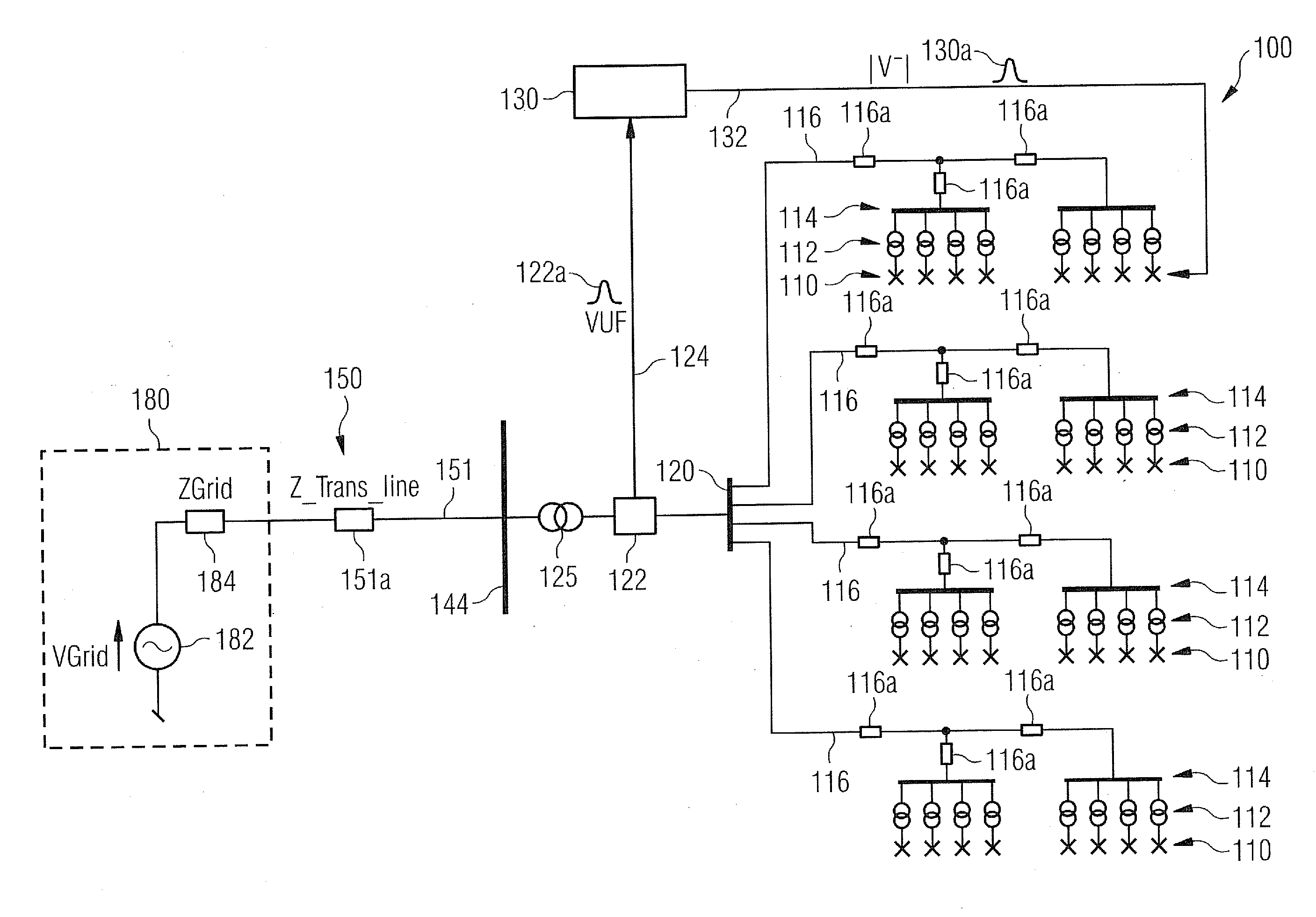
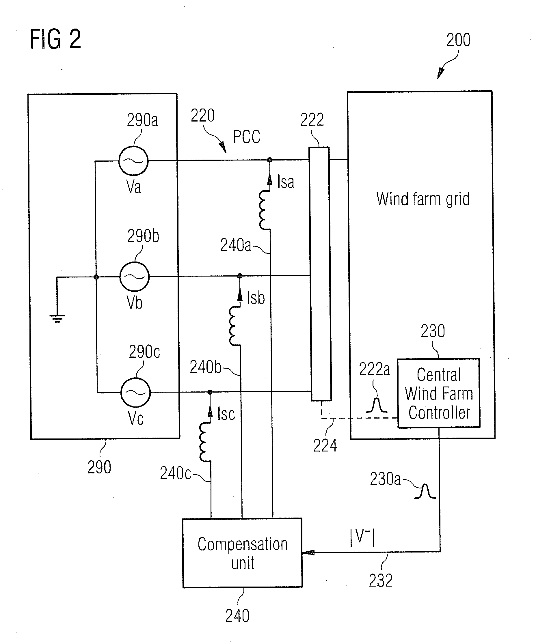
[0020]Descriptive speaking, the Voltage Unbalance Factor (VUF) at the PCC is determined by the measurement device and the VUF is forwarded to the central wind farm controller. Based on the VUF the central wind farm controller causes at least some of the wind turbines and / or an electric unbalancing compensation unit to be operated in such a manner that the electric unbalance at the PCC is reduced at least approximately.
[0024]It is mentioned that in the described embodiment a negative sequence controller is incorporated in the central wind farm controller. This has the advantage that apart from the described measurement device no further experimental effort is necessary in order to accomplish the unbalance mitigation. Therefore, the central wind farm controller, which is essential anyway in order to operate the plurality of wind turbines in a coordinated manner, can be used for effectively reducing an electric unbalancing at the PCC. As a consequence, (a) the voltage quality at the PCC can be improved, (b) harmonic disturbances at the PCC, which are caused by an electric unbalance, can be reduced and / or (c) an additional power loss, which is caused by such harmonics, can be minimized.
[0029]According to a further embodiment of the invention the control unit comprises (a) a proportional (P) control circuit, (b) a proportional derivative (PD) control circuit, (c) a proportional integral derivative (PID) control circuit and / or (d) a Lead / Lag control circuit. This may provide the advantage that the control unit can be realized by known and well established control circuits for reacting on a difference between the measured VUF and the predefined reference VUF.
[0033]The described electric unbalancing compensation unit can be installed in close proximity to the PCC. This electric unbalancing compensation unit receives the control signal from the central wind farm controller and adjusts the injected negative sequence current in such a way that the electric unbalance at the PCC is mitigated.
[0034]According to a further embodiment of the invention the system further comprises a transformer, which is connected between the Point of Common Coupling and a power transmission link connecting the transformer with a substation of a power grid. This may provide the advantage that the voltage at the PCC can be changed or adapted in such a manner that an effective power transmission via the power transmission link can be accomplished. Preferably, the transformer is a voltage step-up transformer, which receives a certain voltage level from the PCC and provides an increased voltage level to the power transmission link. This may provide the advantage that the power loss within the power transmission link can be reduced.
[0035]According to a further embodiment of the invention the measurement device is connected between the Point of Common Coupling and the transformer. This may provide the advantage that the unadulterated voltage signals and its degree of unbalance can be precisely measured directly from the PCC, which in particular in case of a long power transmission link cable represents the crucial “weak point” of the power connection between the wind farm and the substation of the power grid.

Problems solved by technology

This often results in a “weak” grid at the PCC.

Method used


Image

  • System and method for mitigating an electric unbalance of a three-phase current at a point of common coupling between a wind farm and a power grid
  • System and method for mitigating an electric unbalance of a three-phase current at a point of common coupling between a wind farm and a power grid
  • System and method for mitigating an electric unbalance of a three-phase current at a point of common coupling between a wind farm and a power grid

Examples


Embodiment Construction

[0047]The illustration in the drawing is schematically. It is noted that in different figures, similar or identical elements are provided with reference signs, which are different from the corresponding reference signs only within the first digit.

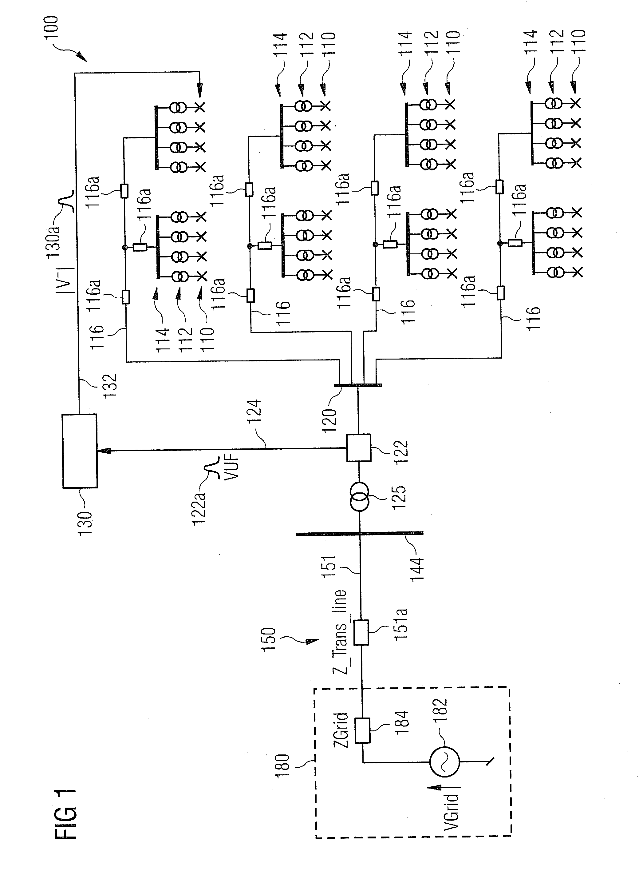
[0048]FIG. 1 shows a wind farm 100, which comprises a plurality of wind turbines 110. Each wind turbine 110, which is illustrated as an “X”, comprises a not depicted individual control unit and a not depicted electric converter. The electric converter converts in a known manner an asynchronous AC power output, which is provided by a wind driven electric generator of the wind turbine 110, firstly into a DC power and secondly into a synchronous AC power output with a given AC frequency. The wind farm 100 further comprises a plurality of transformers 112, wherein respectively one transformer 112 is assigned to one wind turbine 100 and connects the respective wind turbine 110 to a bus bar 114. According to the embodiment described here the elec...


PUM


Abstract

A system is provided for mitigating an electric unbalance of a three-phase current at a Point of Common Coupling being located between a wind farm having a plurality of wind turbines and a power grid. The system includes a measurement device and a central wind farm controller. The measurement device measures the electric unbalance at the Point of Common Coupling and provides a measurement signal being indicative for the measured electric unbalance. The central wind farm controller is coupled to the measurement device and controls the operation of the plurality of wind turbines. In response to the measurement signal the central wind farm provides a control signal for mitigating the electric unbalance at the Point of Common Coupling. Also provided is a corresponding method for mitigating an electric unbalance of a three-phase current and a computer program for controlling and / or for carrying out the mentioned method.

Description

CROSS REFERENCE TO RELATED APPLICATIONS[0001]This application claims priority of European Patent Office application No. 11153557.1 EP filed Feb. 7, 2011. All of the applications are incorporated by reference herein in their entirety.FIELD OF INVENTION[0002]The present invention relates to the technical field of transmitting electrical power, which has been generated by a wind farm comprising a plurality of wind turbines, from the wind farm to a power grid. In particular, the present invention relates to a system and to a method for mitigating an electric unbalance of a three-phase current at a Point of Common Coupling being located between a wind farm comprising a plurality of wind turbines and a power grid. Further, the present invention relates to a computer program, which is configured for controlling the above described electric unbalance mitigating method.ART BACKGROUND[0003]Wind turbines are used to convert wind energy to electrical energy in a clean and efficient way. In a wi...

Claims


Application Information

Patent Timeline
Patent Type & Authority Applications(United States)
IPC IPC(8): G06F1/28
CPCH02J3/26Y02E10/763Y02E40/50H02J3/386H02J2300/28H02J3/381Y02E10/76H02J3/472
Inventor KUMAR, SATHEES
Owner SIEMENS GAMESA RENEWABLE ENERGY AS
Learn More