Table miter saw

a table miter and miter saw technology, which is applied in the field of table miter saws, can solve problems such as errors in cutting cuts, and achieve the effect of precise miter

Inactive Publication Date: 2012-08-16
ROWE JAMES T
View PDF14 Cites 23 Cited by
  • Summary
  • Abstract
  • Description
  • Claims
  • Application Information

AI Technical Summary

Benefits of technology

[0020]A previous miter saw has a motor situated so that the saw is limited to cutting only on the right-hand side. An advantage of the present invention is that the saw design provides clearance on both sides and cuts. Both left and right cuts can be made without further adjustment of blade.
[0021]A typical previous miter saw has preset indent stop settings limiting the adjustment of angle to half-degree settings. An advantage of the present invention is that the saw design provides for infinite settings for the angle degree.
[0022]A typical previous miter saw providing combination cuts on wood exerts the tool away from the wood. An advantage of the present invention is that the tool provides combination cuts while exerting the tool toward the wood.
[0023]A typical miter saw has a 50 degree limit for setting the angle. An advantage of the present invention is the degree setting is unlimited.
[0024]A typical miter saw has been the same with two efforts to mirror two cuts. However, an advantage of the present invention is that the design features provide a precise miter with a pair of mirrored cuts while requiring only one effort to trace and set the miter.
[0025]These and still further objects and advantages of the invention will be apparent to those skilled in the art.

Problems solved by technology

There is always error between setting the cuts because of the readjustment of the guide, even if only slight.

Method used


Image

  • Table miter saw
  • Table miter saw
  • Table miter saw

Examples


Embodiment Construction

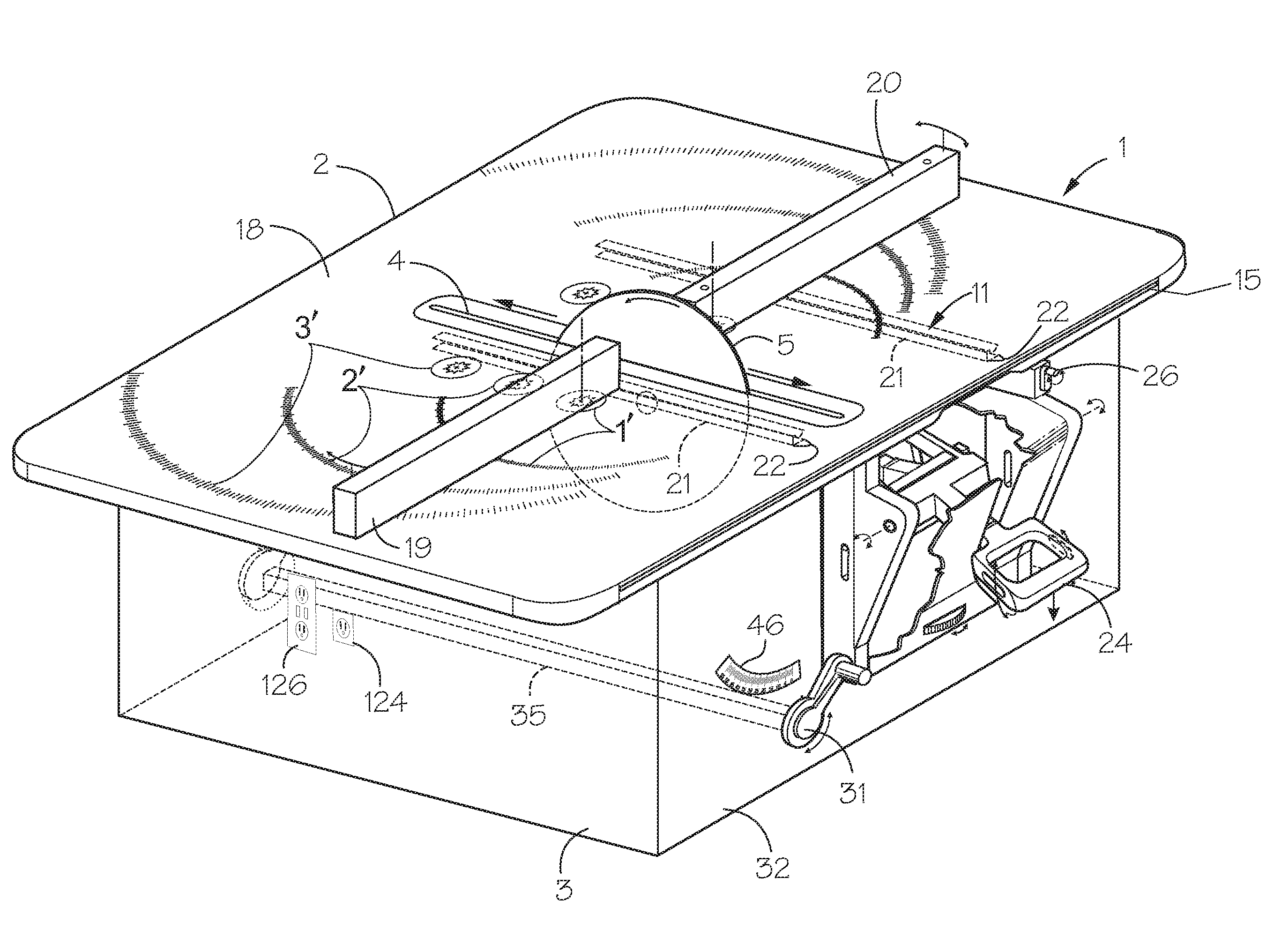
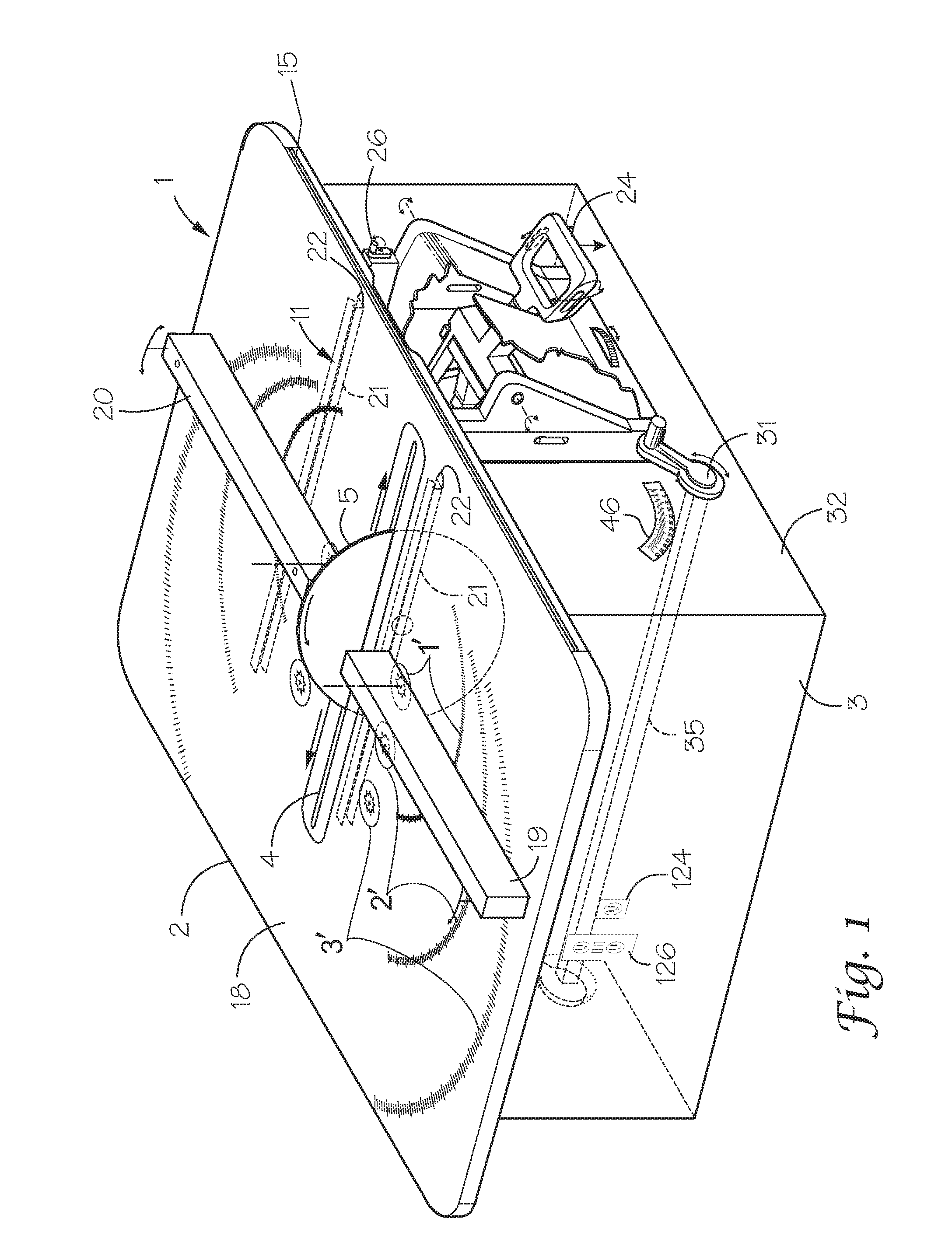
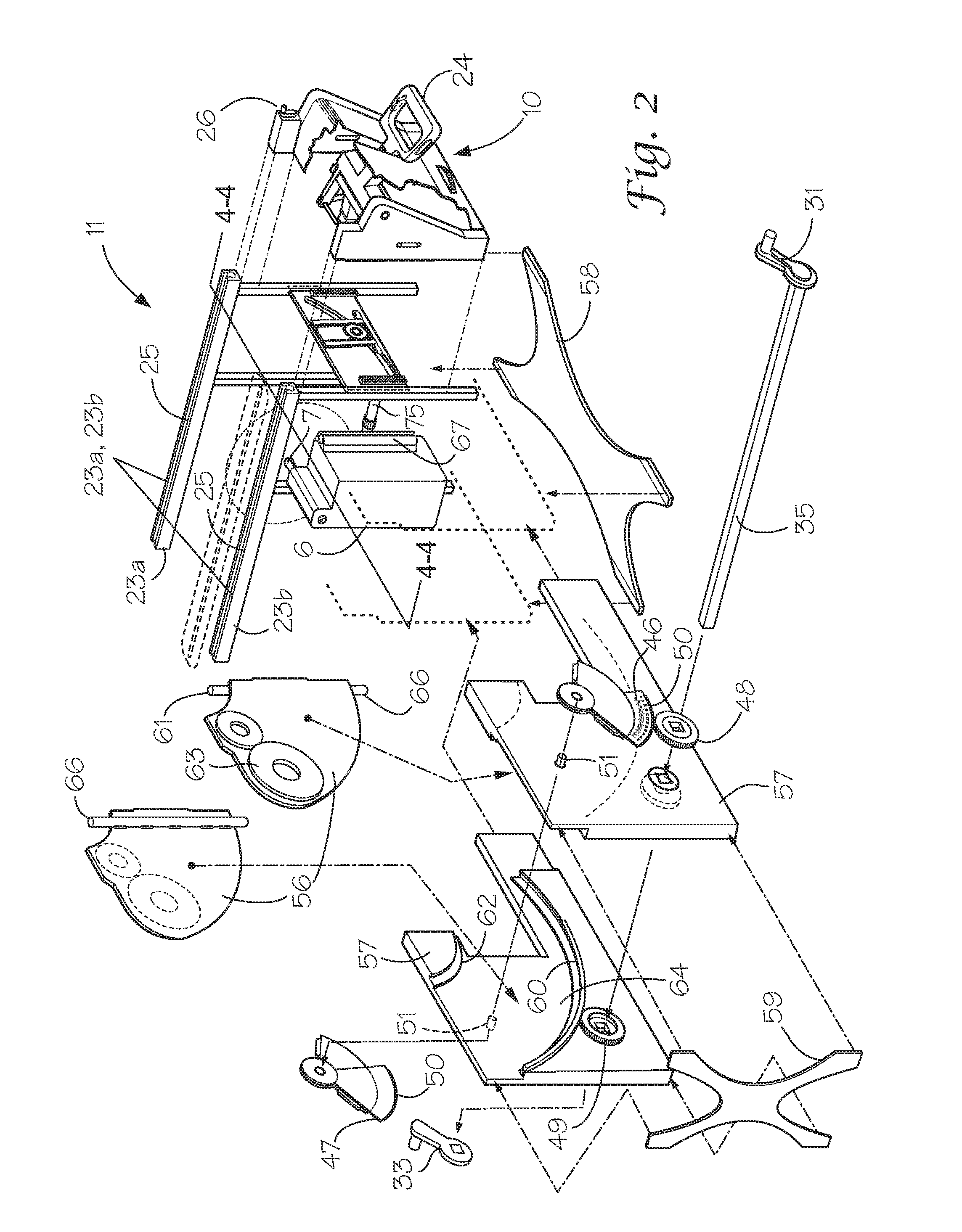
[0069]FIG. 1 shows a saw 1 having a table saw form factor while functioning as an improved miter saw. The improved miter saw has table top 2 supported by frame 3 with an elongate slot 4 arranged near the center of the table top to receive rotating blade 5. The blade 5 is attached to a motor 6 below the table top 2 via an extended motor shaft 7, whereby the motor rotationally drives the blade. The motor 6 and blade 5 are arranged within a motor assembly 8 that is connected to a tilt plate assembly 9 that provides for angular adjustment of the blade. Handle assembly 10 is attached to the motor assembly 8 to raise and lower the blade 5 for height adjustment thereof. The combination of motor 6 and blade 5 and the motor assembly 8 are moved longitudinally below the table top 2 by attaching the tilt plate assembly 9 and handle assembly 10 to the table by a carriage assembly 11. By this arrangement the saw 2 can function as a miter saw or a table saw.

[0070]The table top 2 shown in FIG. 1 m...


PUM

PropertyMeasurementUnit
diameteraaaaaaaaaa
diameteraaaaaaaaaa
angleaaaaaaaaaa

Abstract

A table miter saw includes a motor assembly and tilt plate assembly holding a blade for angular adjustment within a table slot. The blade is mounted to the motor below a table supported by a glide assembly situated within a frame. A handle assembly and the tilt plate assembly are attached to the glide assembly and move the blade longitudinally within the slot. The tilt plates are attached to a shaft between the miter side and the table side of the saw and control knobs operate the shaft to move gears within the tilt plates and change the angle of the blade. The tilt plate assembly moves along the shaft when the blade moves. A brake lock assembly in connection with the control knobs locks the angle of the blade. The height of the blade is set using a blade height lock in connection with the handle assembly for operation during miter cuts, which in addition includes a blade height stop for use during table saw operation. Mirrored miter fences are connected to the table top by star receptacles with gears that operate cooperatively for uniform angle change to make complementary miter cuts. The miter fences receive accessories as needed for complex cuts. The miter fences are removable, and a rip fence is attachable for table saw rip cuts.

Description

PRIORITY CLAIM[0001]The present application claims priority of U.S. provisional patent application Ser. No. 61 / 372,937 filed Aug. 12, 2010 and entitled “Table Miter Saw.”BACKGROUND OF THE INVENTION[0002]Using a miter saws encounters several limitations in the art that need further improvement. For instance miter saws can only cut a limited depth that is insufficient in some cases, and causes a person to resort to hand sawing or adaptation of a table saw to make the cut. Also, a miter saw usually requires the operator to change the miter saw for each left and right miter cut. Each change increases the potential for operator measuring error in making the correct adjustments and handling the work piece with the needed precision for accuracy. Thus, ongoing efforts are made to improve consistency along with efficiency of accomplishing these miter cuts. Further, as the angle of a miter saw changes, some saws have handles that become awkward to use. A non-ergonomic handle can be unsafe to ...

Claims


Application Information

Patent Timeline
Patent Type & Authority Applications(United States)
IPC IPC(8): B23D45/06B23D45/14
CPCB23D45/062B27B27/10B27B27/08B23D59/003Y10T83/04Y10T83/7697
Inventor ROWE, JAMES T.
Owner ROWE JAMES T
Why Eureka
Try Eureka