Structural insulator

a structural insulation and member technology, applied in the field of structural insulation members, can solve the problems of increasing the risk of overloading certain routes increasing the amount of conductor sag, etc., and achieves the effect of increasing the amount of allowable conductor sag, increasing the risk of flashover, and increasing the capacity of overhead line current carrying capacity

Active Publication Date: 2012-08-16
HUBBELL POWER SYST INC
View PDF8 Cites 15 Cited by
  • Summary
  • Abstract
  • Description
  • Claims
  • Application Information

AI Technical Summary

Benefits of technology

[0010]It has now been realized by the inventors that the conductive cross-arms of a conventional tower or pylon can be replaced by cross-arms formed from insulating members, provided that one or more insulating members making up the cross-arm can be formed in such a way that they are resistant to buckling due to the compressive forces which may be experienced by a tower cross-arm in use. By dispensing with a dangling insulator and replacing it by a strong yet lightweight insulating cross-arm, it has been found that the conductors may be suspended directly from the end of the cross-arm, allowing a voltage increase without an increased risk of flashover. If the insulating cross-arm is kept at the same height as a corresponding conventional conductive cross-arm, the conductors are held higher from the ground and do not swing towards the tower owing to a fixed mounting point. Also, by dispensing with a dangling insulator and replacing it by a strong yet lightweight insulating cross-arm, it has been found that the conductors may be suspended directly from the end of the cr

Problems solved by technology

In recent times, as the demand for electricity has increased and more power is generated from dispersed, renewable energy sources, high voltage transmission networks are approaching full capacity with increasing risks of overloading certain routes.
Although it is possible to build new networks, this is costly, time consuming and can meet opposition from local residents.
Increasing the current on an existing circuit can lead to an increased amount of conductor sag through conductor heating and this can cause infringement of ground clearance regula

Method used


Image

  • Structural insulator
  • Structural insulator
  • Structural insulator

Examples


examples

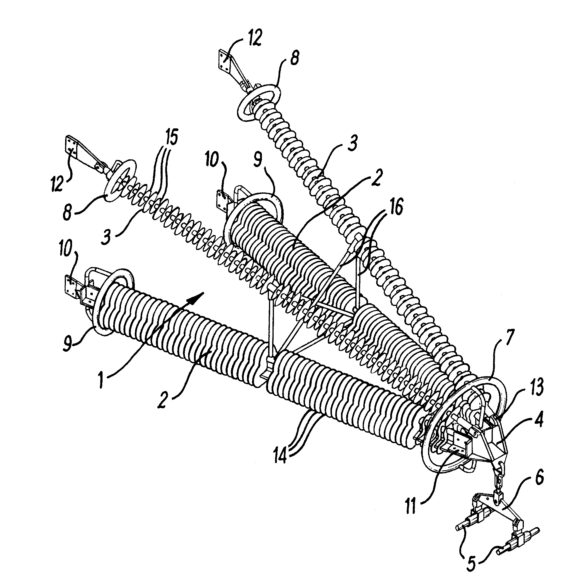
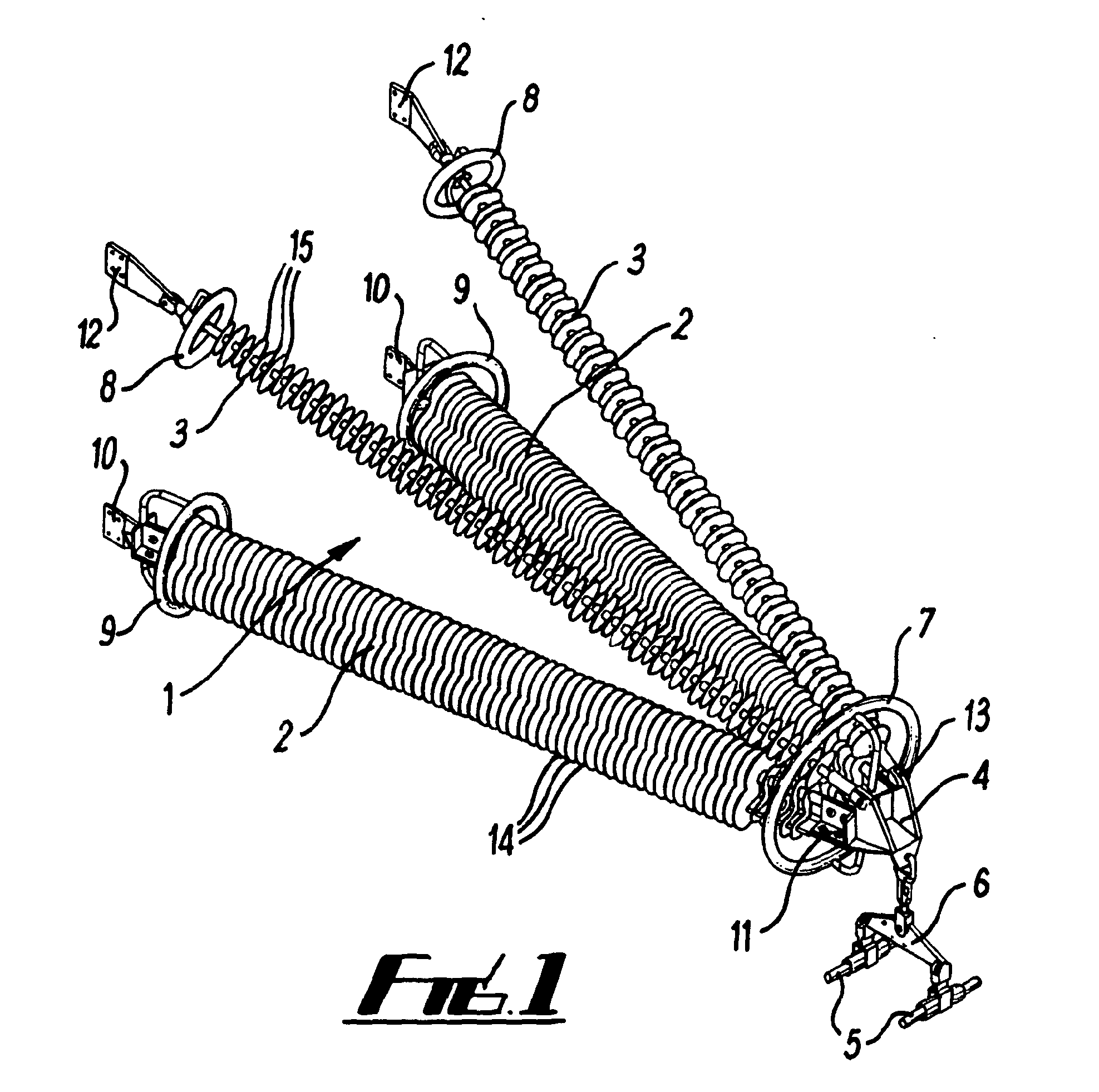
[0087]Specific embodiments of the present invention will now be described, by way of example only, with reference to the accompanying drawings in which:

[0088]FIG. 1 shows an isometric view of a cross-arm according to a first 10 embodiment of the first aspect of the invention,

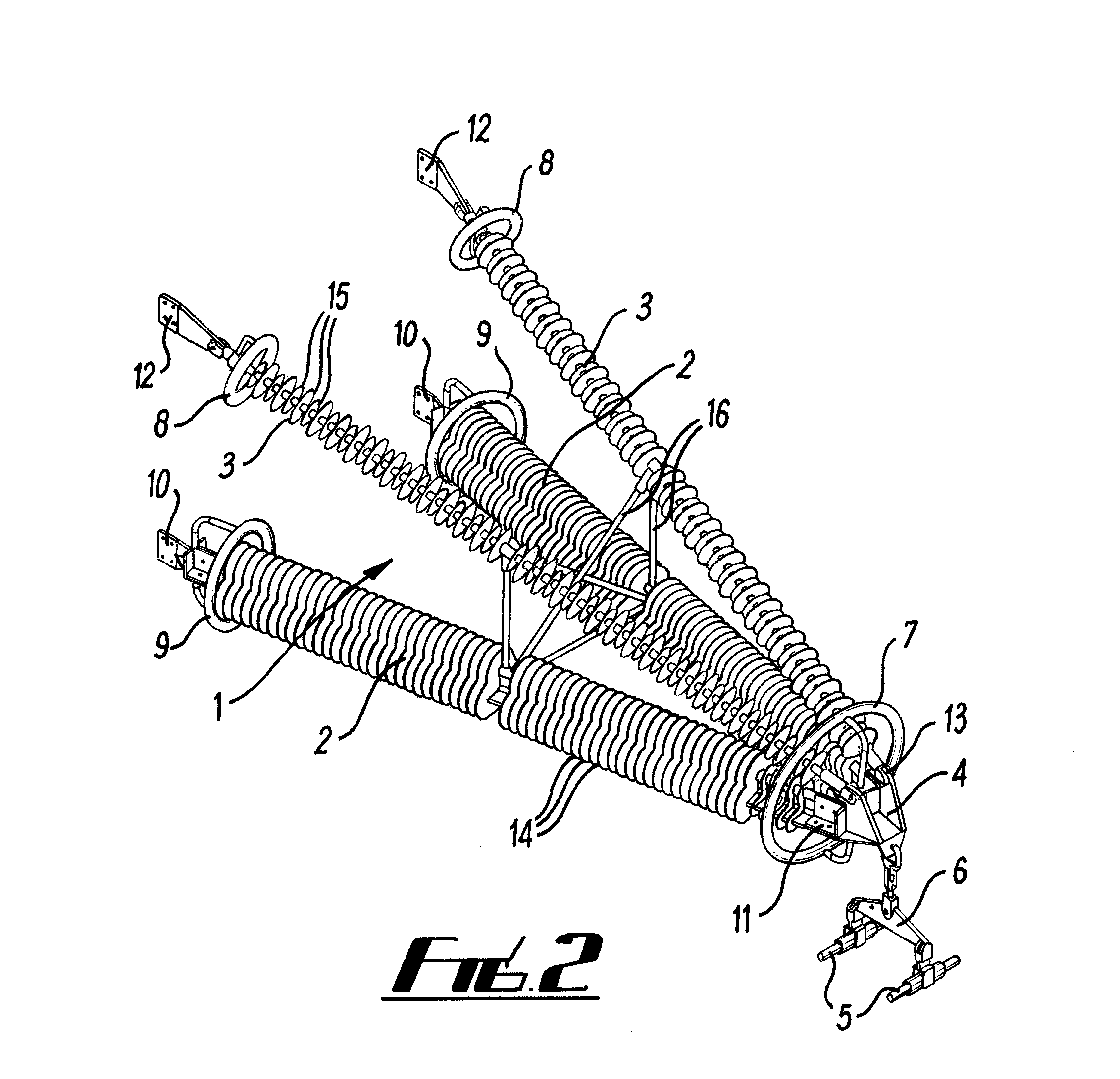
[0089]FIG. 2 shows an isometric view of a cross-arm according to a second embodiment of the first aspect of the invention, where substantially in plane redundant members are included,

[0090]FIG. 3 shows a rear end view of the second embodiment from the base of the cross-arm,

[0091]FIG. 4 shows a side view of the second embodiment of the invention,

[0092]FIG. 5 shows an expanded isometric view showing detail of the apex of the cross-arm of the first or second embodiment,

[0093]FIG. 6 shows an expanded side cross-sectional view along section A-A from FIG. 3 showing detail of the central conductive post of the grading ring at the apex of the cross-arm of the first or second embodiment,

[0094]FIG. 7 shows a cross-section...


PUM


Abstract

An electrically insulating cross-arm for a tower for high-voltage power networks. The cross-arm includes an insulating structural member for attachment to the tower body and to support a conductor cable. The insulating structural member comprises a solid rigid spine extending along a long axis having cross sectional profile, normal to the long axis, having a second moment of area of its cross sectional profile about every axis normal to the long axis and dissecting its centroid has a value of A2/2π or more, where A is the area of the cross sectional profile. The structural member provides resistance to bending and compressive buckling and allows conductors to be safely supported at reduced tower height. T and Y shaped cross sections provide water run-off and inhibition of organic growth. The structural members are also generally useful as insulator members in high voltage power networks.

Description

[0001]This is a continuation of International Application PCT / GB2010 / 001574, with an international filing date of Aug. 20, 2010, and which claims priority from GB 0914678.8 filed on Aug. 21, 2009, and the disclosures of both of these applications from which priority is claimed are incorporated herein by reference.FIELD[0002]The present invention relates to insulating members suitable for use in high voltage electrical power networks and methods for their production. The insulating members are able to withstand compressive buckling and bending forces. The invention also relates to cross-arms for power network towers which incorporate such members and towers with such cross-arms.BACKGROUND[0003]Electricity transmission networks are based on designs dating back to the early 20th century. In recent times, as the demand for electricity has increased and more power is generated from dispersed, renewable energy sources, high voltage transmission networks are approaching full capacity with ...

Claims


Application Information

Patent Timeline
IPC IPC(8): H01B17/16
CPCH02G7/053H02G3/24H01B17/14H01B17/04H01B17/12H01B17/325
Inventor COTTON, IANBAHAROM, MD NOR RAMDON BINROWLAND, SIMON M.CHAMBERS, DAVIDWEATHERBY, NICHOLASTHORNE, MATTHEW
Owner HUBBELL POWER SYST INC
Why Eureka
Try Eureka