Invisible-fluorescent identification tags for materials

Active Publication Date: 2012-08-16
UT BATTELLE LLC
View PDF2 Cites 19 Cited by
  • Summary
  • Abstract
  • Description
  • Claims
  • Application Information

AI Technical Summary

Benefits of technology

[0012]The invention further includes a method of tagging a material substrate including the steps of: providing at least one taggant composition and applying the at least one taggant composition to a material to be tagged, optionally via an

Problems solved by technology

Two technologies have attempted to address the textile need, but were fou

Method used


Image

  • Invisible-fluorescent identification tags for materials
  • Invisible-fluorescent identification tags for materials
  • Invisible-fluorescent identification tags for materials

Examples


Embodiment Construction

[0022]This invention provides a taggant composition for use in marking articles with an identifier for preventing incorrect shipping, counterfeiting, use of non-specified materials, as well as support identification of U.S. materials or goods, quality control, and / or remediation efforts.

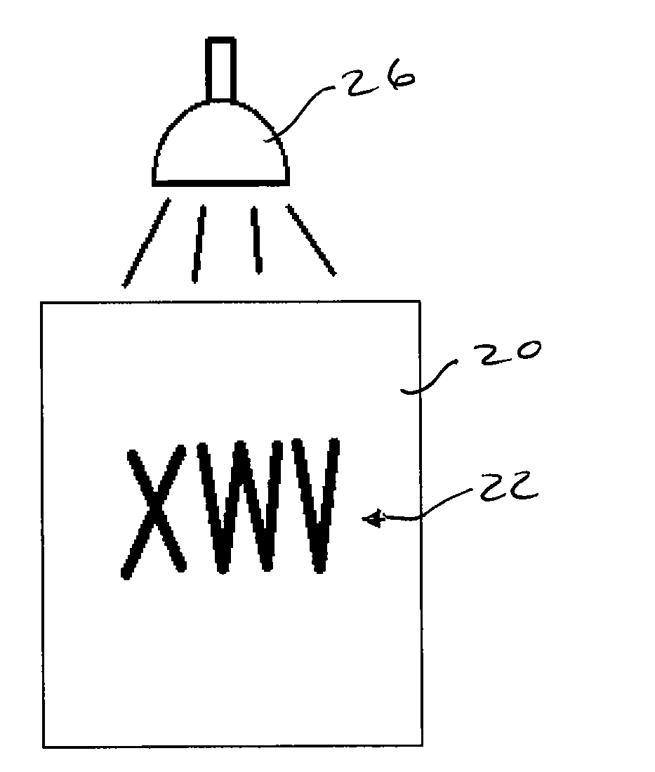
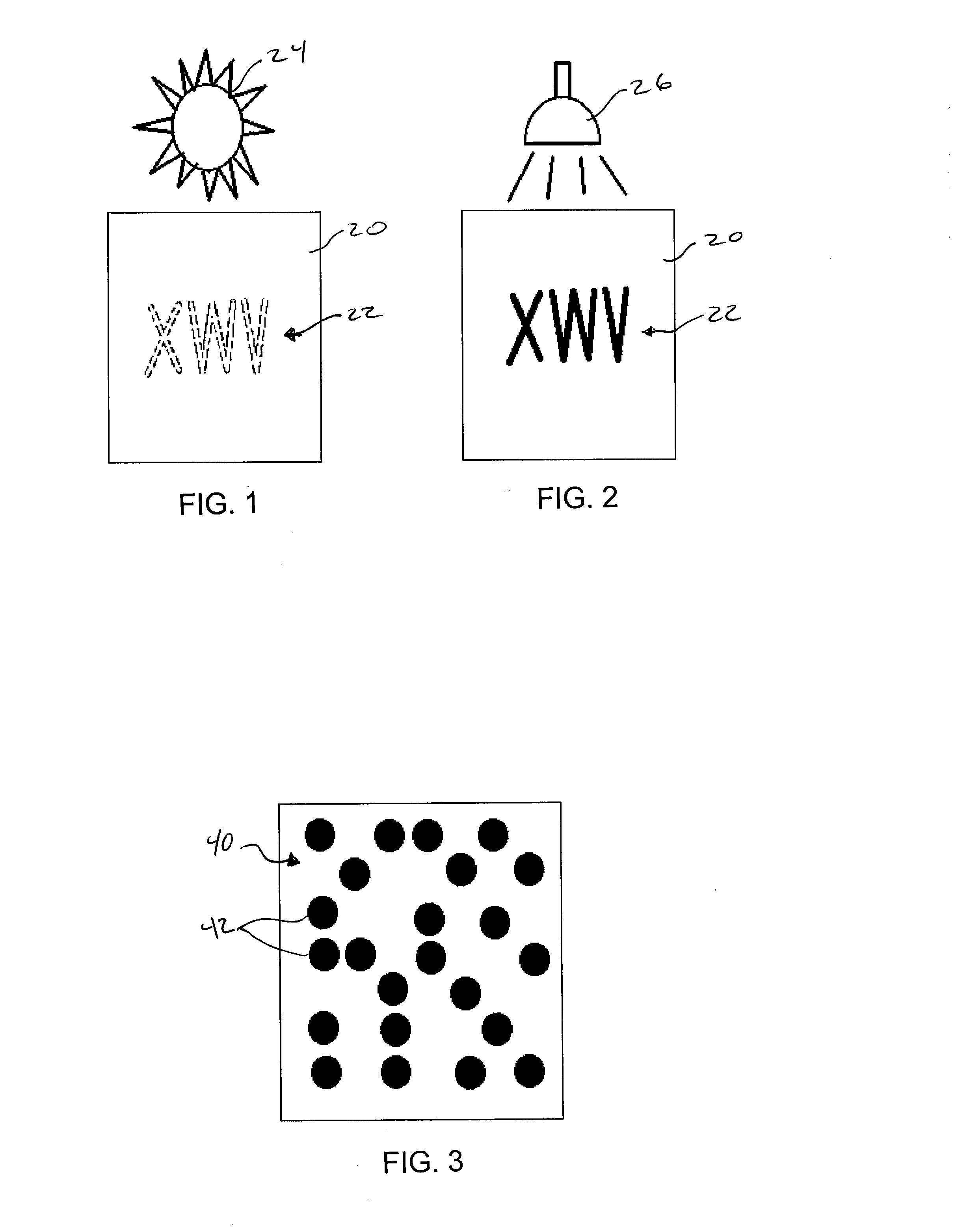
[0023]The taggant composition of this invention includes a taggant material that is invisible in light of the visible spectrum and fluoresces or otherwise becomes detectable under a non-visible excitation energy. FIGS. 1 and 2 illustrate the taggant composition and material according to this invention. In FIGS. 1 and 2, a material 20 is printed, stamped, or otherwise marked with taggant composition to form a code 22 of “XWV”. In FIG. 1, under visible light (represented by the sun 24), the taggant material, and thus code 22, is invisible to the human eye (illustrated by the “phantom” code 22). However, when the article 20 is radiated with non-visible light, such as from infrared light source 26 in FIG...


PUM


Abstract

A taggant composition including a taggant material that is invisible in light of the visible spectrum and fluoresces under a non-visible excitation energy, a binder, and a solvent in which the taggant material and the binder are dissolved. The taggant composition can be printed or otherwise applied to a material such as fabric to provide a detectable and identifiable indicium. A method and apparatus for detecting and decoding the taggant indicium are also provided.

Description

GOVERNMENT RIGHTS[0001]This invention was made with government support under Contract No. DE-AC05-00OR22725 awarded by the U.S. Department of Energy. The government has certain rights in the invention.FIELD OF THE INVENTION[0002]The present invention relates to identification markings for preventing incorrect shipping, counterfeiting, use of non-specified materials, as well as support identification of U.S. materials or goods, quality control, and / or remediation efforts.BACKGROUND OF THE INVENTION[0003]The U.S. Department of Commerce has stated the need to be able to add a tag to identify the point of origin of textiles (raw materials, yarn, fabric, clothing, security documents, currency, etc.), detail manufacturing information, and also for tracking goods. This identification would help to prevent counterfeiting, to enforce international quotas, to collect applicable import duties, to promote manufacturing quality control and e-commerce, and to identify textiles that have been disc...

Claims


Application Information

Patent Timeline
IPC IPC(8): G06K7/10C09K11/02G06K19/06B05D5/00B41F33/00C09K11/06G01J1/58B82Y30/00
CPCG06K7/12G06K19/06037G09F3/0294G09F3/00G06K19/0614
Inventor LEWIS, LINDA A.ALLGOOD, GLENN O.SMITHWICK, III, ROBERT W.
Owner UT BATTELLE LLC
Why Eureka
Try Eureka