Manufacturing method for an optical connector

a manufacturing method and technology of optical waveguides, applied in the field of manufacturing methods of optical waveguides, can solve the problems of increasing the power consumption of electric wiring, the inability to directly use the optical waveguides produced as described above, and the inability to achieve the effect of reducing the cost of production, avoiding adverse effects on the dimensional accuracy and performance of the optical waveguide, and quick and easy utilization

Inactive Publication Date: 2012-08-16
NITTO DENKO CORP
View PDF7 Cites 23 Cited by
  • Summary
  • Abstract
  • Description
  • Claims
  • Application Information

AI Technical Summary

Benefits of technology

[0009]A cost-effective manufacturing method for an optical connector is provided, which enables an optical waveguide to be fixed to a ferrule easily in a short period of time.
[0011]Specifically disclosed is a method of fixing the optical waveguide to the optical connection ferrule made of a resin without using the adhesive or the like. That is, the optical waveguide can be fixed quickly and easily without any adverse effect on the dimensional accuracy and performance of the optical waveguide when an interface portion between the optical waveguide and the ferrule opposed thereto is heated and fused utilizing a laser beam in a wavelength range in which the laser beam is not absorbed by the material that forms the optical waveguide (near infrared range).
[0013]As described above, in the manufacturing method for an optical connector, in the state in which the end portion of the transparent optical waveguide is fitted into the optical waveguide fitting groove of the optical connection ferrule made of a resin, the laser beam having the predetermined wavelength is applied from above the fitting groove (opening side) to the bottom surface of the above-mentioned fitting groove through the above-mentioned optical waveguide. As a result, the above-mentioned optical waveguide can be fused and fixed to the fitting groove of the ferrule quickly and easily utilizing the heat generation due to the absorption of the laser beam.
[0014]Further, in the manufacturing method for an optical connector, the above-mentioned laser beam passes through the optical waveguide without being absorbed by the optical waveguide, and hence no adverse effect is imposed on the dimensional accuracy and performance of the optical waveguide. Moreover, the heat is not directly applied to the optical waveguide, and hence, during the fixing work, the position thereof (aligned position) is not shifted. Further, the adhesive or the like is not used, and hence there occurs no positional shift due to, for example, contraction at the time of curing the adhesive. Accordingly, the manufacturing method for an optical connector enables precise and accurate fixing of the end portion of the optical waveguide to the predetermined position in the fitting groove of the above-mentioned ferrule.
[0015]Further, it is only necessary to use the minimal amount of the fixing adhesive or the like merely for the temporary fixing, and hence no blur or smear from the adhesive or the like is generated in the leading end surface of the ferrule. Thus, the manufacturing method for an optical connector has such advantages that the cost for the above-mentioned fixing agent can be reduced and the polishing step after the optical waveguide is fixed can be omitted.
[0016]Further, in the manufacturing method for an optical connector, in a case where the laser beam to be used for fixing the above-mentioned optical waveguide is a near infrared laser beam having a wavelength of from 800 nm to 2,000 nm, which is not easily absorbed particularly by the optical waveguide, it is possible to further suppress the adverse effect on the dimensional accuracy and performance of the optical waveguide, and to selectively and efficiently heat the bottom surface (interface between the ferrule and the optical waveguide) of the fitting groove of the above-mentioned optical connection ferrule made of a resin.

Problems solved by technology

In recent years, integration and increase in scale of electronic devices have raised problems of heat generation and increased power consumption of electric wiring, which is widely used for connection between boards or chips on a board in the device.
Note that the optical connector produced as described above cannot directly be put into use in many cases because an excessive portion of the above-mentioned used adhesive or the like projects as a “blur” at the leading end surface (optical connection surface) of the optical connector, and because the above-mentioned adhesive or the like adheres to the end surface of the optical waveguide exposed at the leading end surface.
However, as described above, the conventional manufacturing method for an optical connector, in which the optical waveguide is fixed with a fixing agent such as an adhesive, requires material cost for the fixing agent, and time and labor for fixing work (increases the number of steps).
Further, the polishing step needs to be performed after the optical waveguide is fixed, which leads to a problem of an increase in cost.

Method used


Image

  • Manufacturing method for an optical connector
  • Manufacturing method for an optical connector
  • Manufacturing method for an optical connector

Examples


examples

[0047]Next, an example is described together with a comparative example. Note that, the present invention is not limited to the following example.

[0048]In this example, a polymer optical waveguide was manufactured through photolithography, and one end portion of the polymer optical waveguide was fixed to a commercial PMT ferrule using a near infrared laser beam. Further, the same optical waveguide was used and the end portion thereof was fixed to the PMT ferrule with an adhesive to manufacture a comparative example of the optical connector. The example and the comparative example were compared to each other on an insertion loss “before mounting the ferrule” and an insertion loss “after mounting the ferrule” (in the comparative example, after carrying out polishing). Note that, the insertion loss was measured in conformity with JIS C 5961 “test method for optical fiber connector”.

[0049]In advance of the example, an optical waveguide for the test was first manufactured.

[Forming Materi...

example

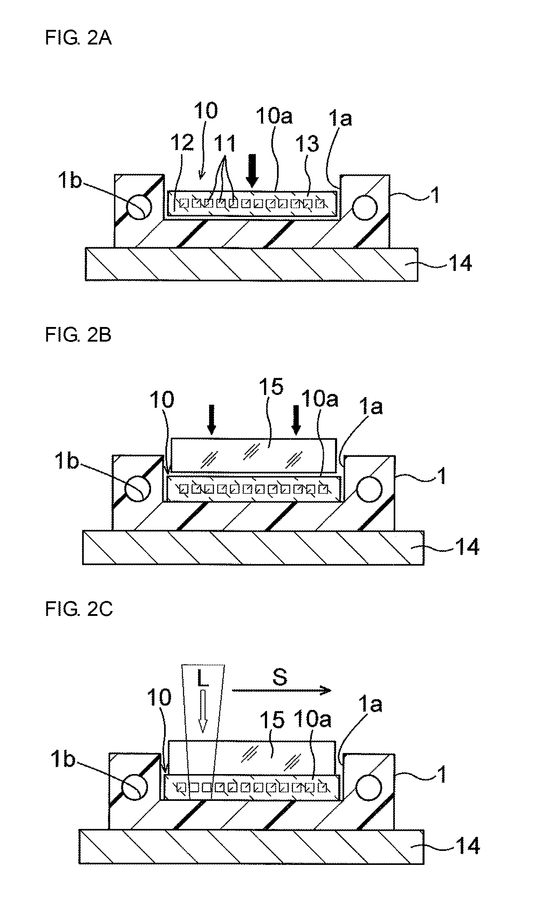
[0065]One end portion (longitudinal end portion) of the strip-like optical waveguide manufactured as described above was fitted into an optical waveguide fitting groove of the ferrule as in the manufacturing method of the first embodiment (see FIG. 2A). Then, the position of the end portion of the optical waveguide was adjusted for positional alignment thereof, and the end portion was pressed by a glass plate, to thereby perform temporary fixing (see FIG. 2B). The laser beam L was applied from above the fitting groove to the bottom surface of the fitting groove through the optical waveguide, and the bottom surface was left for cooling, to thereby firmly fix the end portion of the above-mentioned optical waveguide to the ferrule. Note that, in this example, no adhesive was used in the temporary fixing of the above-mentioned end portion.

[0066]The applied laser beam was a near infrared laser beam having a wavelength of 940 nm, and was applied so that the focal point of the laser beam (...


PUM


Abstract

Provided is a cost-effective manufacturing method for an optical connector, which enables an optical waveguide to be fixed to a ferrule easily in a short period of time. A manufacturing method for an optical connector includes: fitting an end portion of a transparent optical waveguide into an optical waveguide fitting groove of an optical connection ferrule made of a resin; and fusing and fixing the end portion of the transparent optical waveguide to the optical connection ferrule by applying a laser beam having a predetermined wavelength downward from above the optical waveguide fitting groove toward the transparent optical waveguide, so that the laser beam reaches a bottom surface of the optical waveguide fitting groove.

Description

BACKGROUND OF THE INVENTION[0001]1. Field of the Invention[0002]The present invention relates to a manufacturing method for an optical connector, which is obtained by integrally mounting an optical connection ferrule, such as a PMT ferrule, to a leading end portion of an optical waveguide.[0003]2. Description of the Related Art[0004]In recent years, integration and increase in scale of electronic devices have raised problems of heat generation and increased power consumption of electric wiring, which is widely used for connection between boards or chips on a board in the device. Therefore, there has been developed an optical wiring (optical interconnection) technology, in which such electric wiring is replaced with a lightweight, flexible polymer optical waveguide which generates a smaller amount of heat (see Japanese Patent Application Laid-open Nos. Hei 10-186187 and 2000-2820).[0005]An optical connector (optical waveguide connector) to be used in the optical wiring for connection...

Claims


Application Information

Patent Timeline
Patent Type & Authority Applications(United States)
IPC IPC(8): G02B6/26
CPCG02B6/3855G02B6/3885G02B6/4292G02B6/4246G02B6/4249G02B6/4214
Inventor NAGAFUJI, AKIKOMATSUO, NAOYUKISHIMODA, MAYU
Owner NITTO DENKO CORP
Why Eureka
Try Eureka