Charge-discharge control circuit, semiconductor integrated circuit, method of controlling charging and discharging, and charging and discharging control program

Active Publication Date: 2012-08-16
MITSUMI ELECTRIC CO LTD
View PDF2 Cites 27 Cited by
  • Summary
  • Abstract
  • Description
  • Claims
  • Application Information

AI Technical Summary

Benefits of technology

[0070]According to the embodiment, it is possible to improve efficiency of use of t

Problems solved by technology

Therefore, the current which should be supplied to a load is consumed by the bypass circuit 20 to reduce the efficiency of use of the electric charge stored in the ce

Method used


Image

  • Charge-discharge control circuit, semiconductor integrated circuit, method of controlling charging and discharging, and charging and discharging control program
  • Charge-discharge control circuit, semiconductor integrated circuit, method of controlling charging and discharging, and charging and discharging control program
  • Charge-discharge control circuit, semiconductor integrated circuit, method of controlling charging and discharging, and charging and discharging control program

Examples


first embodiment

[0105]The first embodiment is described with reference to drawings. FIG. 3 is a diagram for explaining a charge-discharge control circuit of the first embodiment.

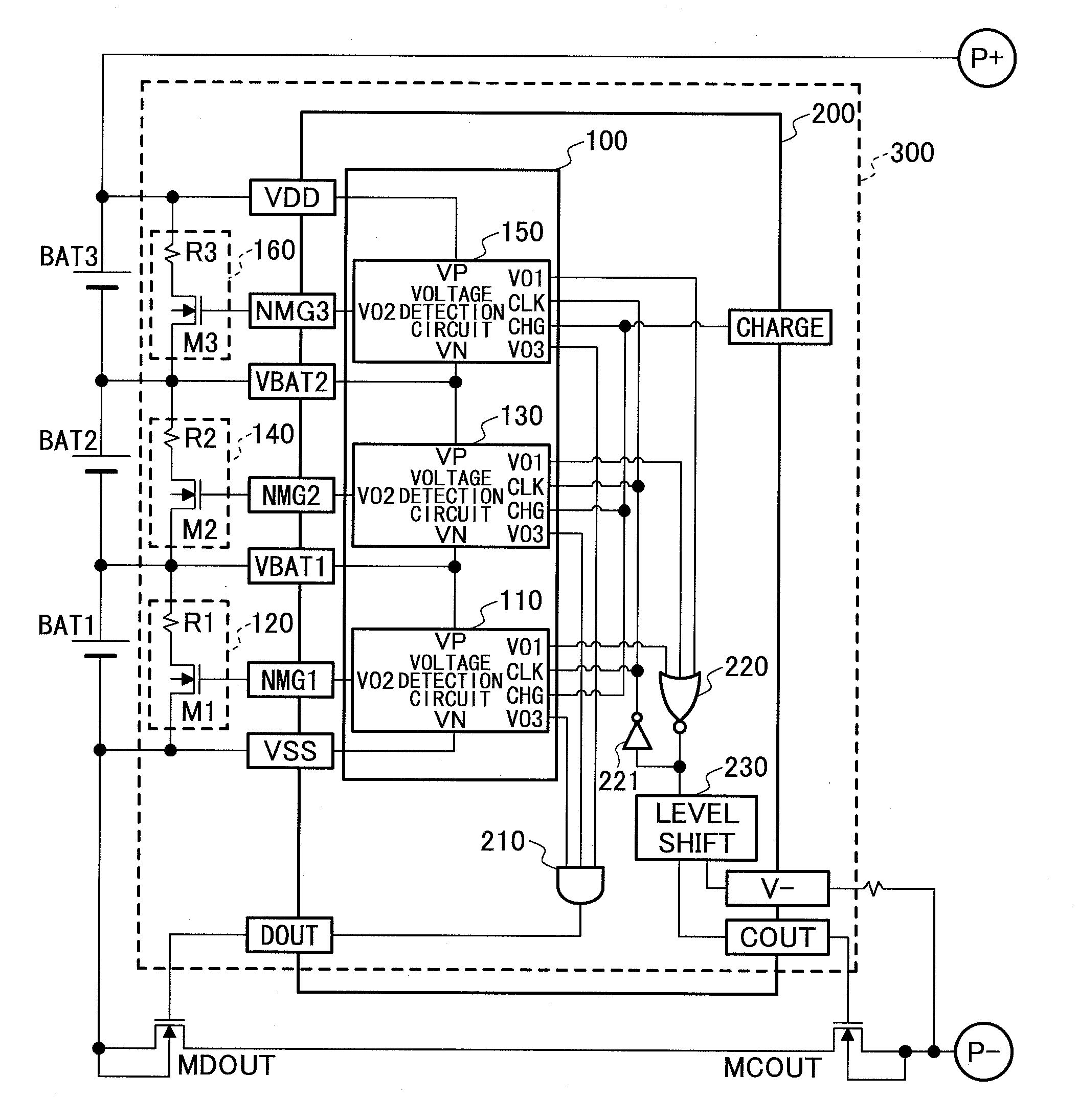
[0106]A charge-discharge control circuit 300 of the embodiment is connected between plural cells which are connected in series and a load, and controls charging and discharging of the plural cells. The charge-discharge control circuit 300 of the embodiment controls charging and discharging of the plural cells by controlling ON / OFF of a transistor for controlling charging MCOUT and a transistor for controlling discharging MDOUT connected in series between an anode side of the plural cells and an anode side of the load.

[0107]The charge-discharge control circuit 300 of the embodiment includes a voltage detection circuit 100, bypass circuits 120, 140 and 160, an AND circuit 210, a NOR circuit 220, an INV circuit 221, and a level shift circuit 230.

[0108]The voltage detection circuit 100 includes plural voltage detection circuits...

second embodiment

[0152]The second embodiment is described with reference to drawings. In the second embodiment, detection whether the cells reach the cell balance detection voltage is prevented except for the cell that reaches the cell balance detection voltage first.

[0153]In this embodiment, as the bypass circuit connected to the cell which has reached the cell balance detection voltage first is switched on in the next charging operation to reduce the charge current, it can be suppressed that the same cell continuously reaches the cell balance detection voltage first. Further in this embodiment, as the detection whether the cells, other than the cell which reaches the cell balance detection voltage first, reach the cell balance detection voltage is prevented, the bypass current only flows through one of the bypass circuits in the charging operation. Therefore, the current consumed as the bypass current can be reduced.

[0154]A charge-discharge control circuit 300A of the embodiment is explained in th...

third embodiment

[0186]The third embodiment is described with reference to drawings. In the third embodiment, a point where a single charge-discharge control circuit controls charging and discharging of a single cell is different from the second embodiment. In the following explanation of the embodiment, only the different points from the second embodiment are explained.

[0187]A charge-discharge control circuit 300B of the embodiment is explained with reference to FIG. 13. The charge-discharge control circuit 300B of the embodiment controls charging and discharging of a single cell. FIG. 13 is a diagram for explaining the charge-discharge control circuit of the third embodiment.

[0188]The charge-discharge control circuit 300B of the embodiment includes a bypass circuit 31, a voltage detection circuit 400, AND circuits 311 and 318, a NOR circuit 314, an OR circuit 319, inverters 312, 315 and 317, a memory circuit 310, rising edge generators 330 and 350, falling edge generators 340 and 360, and a logic ...


PUM


Abstract

A charge-discharge control circuit includes a cell balance detection circuit that detects that a voltage of a cell reaches a predetermined voltage; a memory circuit that stores the cell that reaches the predetermined voltage first among plural of the cells; bypass circuits respectively connected to the plural cells in parallel, each of the bypass circuits including a switch unit for bypassing the current that flows through the corresponding cell when charging; and a control circuit that controls the switch units, wherein the control circuit controls the switch unit based on the cell stored in the memory circuit so that an ON/OFF status of the switch unit is maintained from a start to an end of a next charging operation subsequent to a charging operation during which the cell is stored in the memory circuit.

Description

TECHNICAL FIELD[0001]The present invention relates to a charge-discharge control circuit that controls charging and discharging of a secondary battery including plural cells, a semiconductor integrated circuit on which the charge-discharge control circuit is mounted, a method of controlling charging and discharging by the charge-discharge control circuit, and a charging and discharging control program.BACKGROUND ART[0002]There exists a battery pack of a secondary battery using a lithium ion battery or the like configured by plural secondary batteries (hereinafter, referred to as “cell”) connected in series. For such a battery pack, when the voltage difference between cells becomes large by repeating charging and discharging, self-discharge or the like, the capacity balance between the cells (hereinafter, referred to as “cell balance”) may not maintained. When the cell balance is not maintained, the charging capacity capable of being used as a battery pack is lowered to decrease effi...

Claims


Application Information

Patent Timeline
IPC IPC(8): H02J7/00H02J7/02
CPCH01M10/441H02J7/0016H01M10/482Y02E60/10
Inventor NISHIZAWA, AKIHIROTAKEDA, TAKASHI
Owner MITSUMI ELECTRIC CO LTD
Why Eureka
Try Eureka