Method for Representing Objects with Concentric Ring Signature Descriptors for Detecting 3D Objects in Range Images

Active Publication Date: 2012-08-16
MITSUBISHI ELECTRIC RES LAB INC
View PDF7 Cites 25 Cited by
  • Summary
  • Abstract
  • Description
  • Claims
  • Application Information

AI Technical Summary

Problems solved by technology

Prior art object detection methods generally assume the availability of a 3D surface mesh, and complete 3D models, and therefore those methods cannot be readily extended to 2.5 range images.
Nearby objects can also act as background clutter interfering with the detection method.
Viewpoint and scale changes exhibit high appearance variation and ambiguity.
Range scanners have a limited spatial resolution because the surface is only scanned at discrete points, and fine details in the objects is usually lost or blurred.
For some scanners, the sampling resolution varies greatly along different axes, and re-sampling of a 3D point clouds is difficult and possibly leads to distortion of the surface topology.
High-speed range scanners introduce significant noise in the range measurement, causing parts of the scene having incomplete observations.
However, local descriptors are not usefu

Method used


Image

  • Method for Representing Objects with Concentric Ring Signature Descriptors for Detecting 3D Objects in Range Images
  • Method for Representing Objects with Concentric Ring Signature Descriptors for Detecting 3D Objects in Range Images
  • Method for Representing Objects with Concentric Ring Signature Descriptors for Detecting 3D Objects in Range Images

Examples


Example

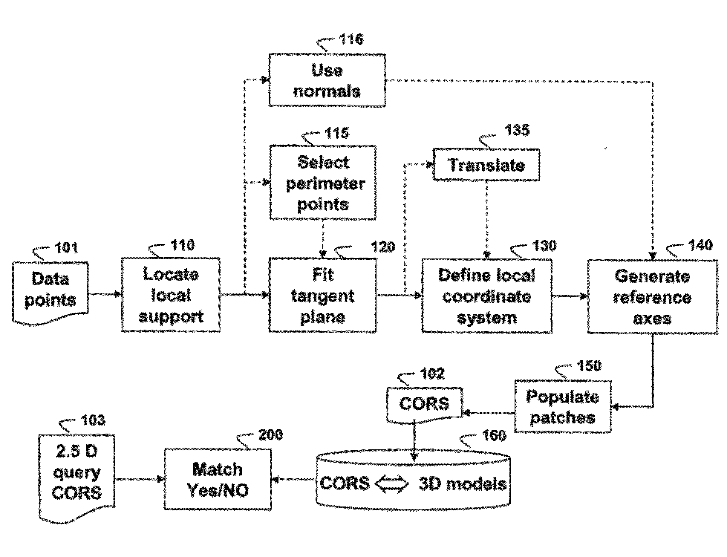
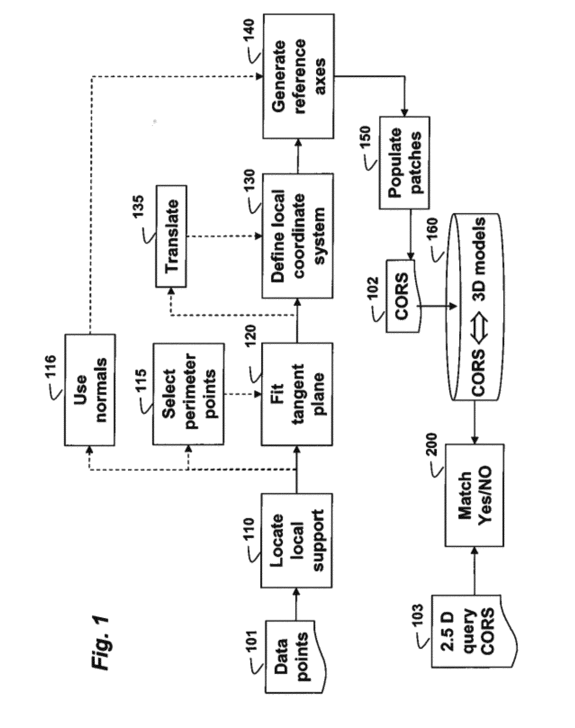
[0044]The embodiments of our invention provide a method for representing a 3D object with a descriptor, and detecting similar objects in a query 2.5D range images using the descriptor. The 2.5 range images can be acquired by a scanner. The 3D object is modeled by a 3D point cloud. As defined herein, object detection generally includes object shape matching, object recognition, and object registration, and a point cloud is defined a set of vertices in a three-dimensional coordinate system (x, y, z) intended to be representative of an external surface of the object. More specifically, the point cloud is sparse, see U.S. patents and Publication U.S. Pat. No. 7,605,81 7,856,125, and 20080310757.

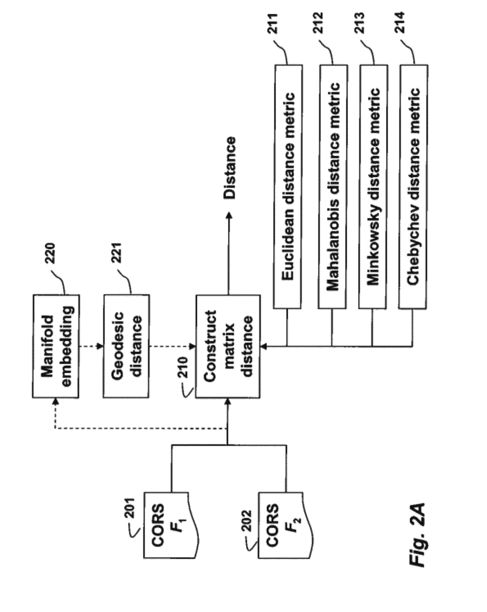
[0045]We describe a 3D descriptor, which represents local topologies within a set of folded concentric rings, by distances from local data points to a projection plane. We call this descriptor a Concentric Ring Signature (CORS). The CORS are stored in a database and associated with the correspond...


PUM


Abstract

A 3D object is represented by a descriptor, wherein a model of the 3D object is a 3D point cloud. A local support for each point p in the 3D point cloud is located, and reference x, y, and z axes are generated for the local support. A polar grid is applied according to the references x, y, and z axes a along an azimuth and a radial directions on an xy plane centered on the point p such that each patch on the grid is a bin for a 2D histogram, wherein the 2D histogram is a 2D matrix F on the grid and each coefficient of the 2D matrix F corresponds to the patch on the grid. For each grid location (k, l), an elevation value F(k, l) is estimated by interpolating the elevation values of the 3D points within the patches to produce the descriptor for the point p.

Description

FIELD OF THE INVENTION [0001]This invention relates representing objects with descriptors, and more particularly to detecting objects in 2.5D range images using the descriptors.BACKGROUND OF THE INVENTION[0002]Using a database of 3D models of objects, it is desired to provide a method for detecting objects in a query 2.5 D range image acquired by a scanner of a 3D scene. In the 2.5D range image, every scanned point (pixel) (x, y) on a surface of an object is associated with one depth value z, i.e., where z is the distance from the scanner to the point.[0003]Object Detection[0004]As defined herein, object detection generally includes object shape matching, object recognition, and object registration.[0005]Point Cloud[0006]A point cloud is a set of vertices in a three-dimensional coordinate system. The vertices are usually defined by (x, y, z) coordinates, and typically represent the external surface of the object. The point clouds used herein are generated by a scanner. Scanners auto...

Claims


Application Information

Patent Timeline
IPC IPC(8): G06T15/00
CPCG06K9/6214G06K9/00214G06V20/653G06V10/76
Inventor PORIKLI, FATIHNGUYEN, HIEN
Owner MITSUBISHI ELECTRIC RES LAB INC
Why Eureka
Try Eureka