Method for Enhancing Depth Images of Scenes Using Trellis Structures

Inactive Publication Date: 2012-08-16
MITSUBISHI ELECTRIC RES LAB INC
View PDF3 Cites 11 Cited by
  • Summary
  • Abstract
  • Description
  • Claims
  • Application Information

AI Technical Summary

Benefits of technology

[0014]The embodiments of the invention provide a trellis-based view synthesis method that overcomes the above limitations in depth images and can reduce artifacts in the rendered images. With this method, a candidate set of depths are identified for each pixel that needs to be warped, based on an estimated depth for that pixel, as well as neighboring depths. The cost for eac

Problems solved by technology

However, a quality of the rendered images is very sensitive to the quality of the depth image, which is typically estimated by an error prone process.
Furthermore, per-pixel depth i

Method used


Image

  • Method for Enhancing Depth Images of Scenes Using Trellis Structures
  • Method for Enhancing Depth Images of Scenes Using Trellis Structures
  • Method for Enhancing Depth Images of Scenes Using Trellis Structures

Examples


first embodiment

[0050]In the first embodiment as shown in FIG. 7, local optimization is performed with limited complexity. In this embodiment, candidate depth selection does not depend on the selection of the optimal depth candidates from previous pixels. So, the candidate depth assignment and evaluation of the pixels can be performed in parallel. A step-by-step description of this implementation is described below.

[0051]The steps shown in various Figs. can be performed in a processor connected to a memory and input / output interfaces as known in the art. The virtual image can be rendered and outputted to a display device. Alternatively, the steps can be implemented in a system using means comprising discrete electronic components in a video encoder or decoder (codec). More specifically, in the context of a video encoding and decoding system (codec), the method described in this invention for generating virtual images can also be used to predict the images of other views. See for example U.S. Pat. N...

second embodiment

[0055]FIG. 8 shows a second embodiment, which is also a local optimization with limited complexity. In this implementation, the candidate depth assignments in a column of the trellis depend on the optimal depth selection for the immediate previous pixel or column in the trellis. Below is a step-by-step description of this implementation.

[0056]Step 801: we initialize the index i.

[0057]Step 802: Identify candidate depths for pixel i. In this step, we include three depth candidates, which are selected in a similar way as the embodiment shown in FIG. 7. However, when deriving depth B and C, the optimal depths from previous pixels are used, which can be different from what is signaled in the depth image.

[0058]Step 803: Evaluate the cost for each depth candidate of pixel i.

[0059]Step 804: Compare the costs of all the depth candidates and determine the least cost for pixel i.

[0060]Step 805: If there are more pixels not processed in the trellis, then increase i 806 by one, and iterate.

third embodiment

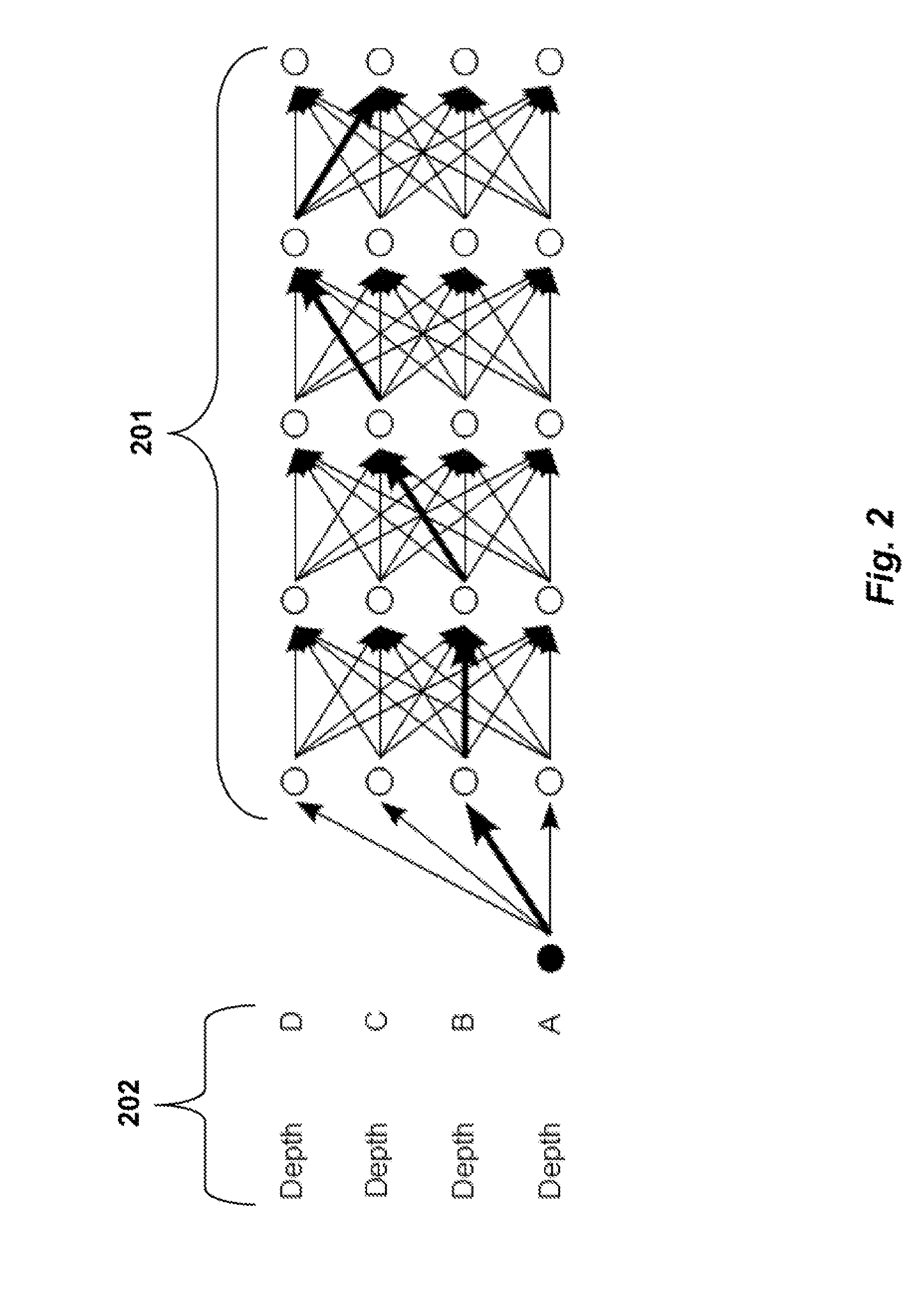
[0061]In the first two embodiments, the optimal depth candidate is selected in the trellis column by column by evaluating a local cost function. In the third embodiment, the optimal path across the trellis, which is a combination of depth candidates from the columns, is determined. A path cost is defined as the sum of the node costs within the path.

[0062]A node can have different costs in different paths. This embodiment is shown in FIG. 9. The procedure has two loops iterating over i and p. The outer loop is over all possible paths, while the inner loop is for all nodes in one possible path.

[0063]For each potential path, we identify 901 and evaluate 902 the candidate depth for the nodes sequentially in the path. The depth candidate assignments are determined as follows. Determine 903 if there are more pixels in the path.

[0064]If the next node locates at row “Depth A,” then the node is set to the depth as signaled in the depth image. If the node locates at row “Depth B,” then we sel...


PUM


Abstract

An image for a virtual view of a scene is generated based on a set of texture images and a corresponding set of depth images acquired of the scene. A set of candidate depths associated with each pixel of a selected image is determined. For each candidate depth, a cost that estimates a synthesis quality of the virtual image is determined. The candidate depth with a least cost is selected to produce an optimal depth for the pixel. Then, the virtual image is synthesized based on the optimal depth of each pixel and the texture images. The method also applies first and second depth enhancement before, and during view synthesis to correct errors or suppress noise due to the estimation or acquisition of the dense depth images and sparse depth features.

Description

RELATED APPLICATION[0001]This is a Continuation-in-Part application of U.S. application Ser. No. 13 / 307,936 “Method for Generating Virtual Images of Scenes Using Trellis Structures,” filed Nov. 30, 2011, by Tian et al, which is a Continuation-in-Part application of U.S. application Ser. No. 13 / 026,750, “Method for Generating Virtual images of Scenes Using Trellis Structures,” filed Feb. 14, 2011, by Tian et al.FIELD OF THE INVENTION[0002]This invention relates generally to depth image based rendering (DIBR), and more particularly to a method for enhancing depth images using a trellis structure.BACKGROUND OF THE INVENTION[0003]A 3D display presents an image of a different view of a 3D scene for each eye. In conventional stereo systems, images for left and right views are acquired, encoded, and either stored or transmitted, before decoded and displayed. In more advanced systems, a virtual image with a different viewpoint than the existing input views can be synthesized to enable enhan...

Claims


Application Information

Patent Timeline
IPC IPC(8): G06T17/30
CPCG06T15/205
Inventor TIAN, DONGWANG, YONGZHEVETRO, ANTHONY
Owner MITSUBISHI ELECTRIC RES LAB INC
Why Eureka
Try Eureka