
Method and device for clarification of liquids, particularly water, loaded with material in suspension

Inactive Publication Date: 2007-02-13
ONDEO DEGREMONT INC
View PDF10 Cites 8 Cited by
  • Summary
  • Abstract
  • Description
  • Claims
  • Application Information

AI Technical Summary

Benefits of technology

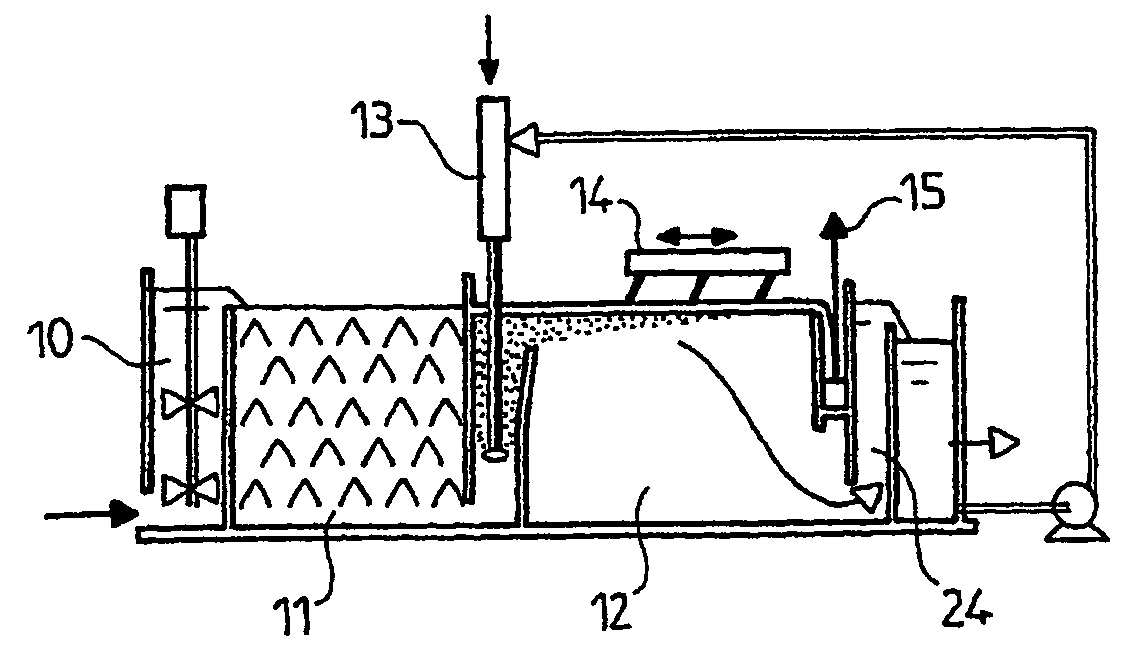
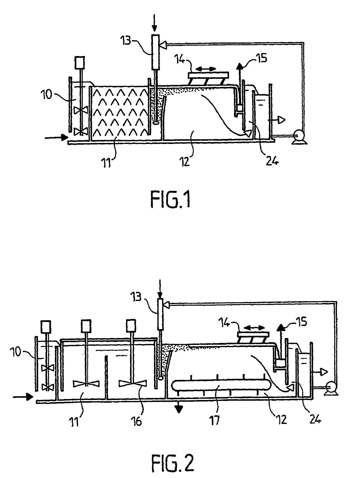
[0021]Starting with the prior art mentioned above, the present invention proposes to solve the technical problem consisting in using flotation to treat waters containing not only floatable particles, but also heavy and unfloatable particles, while maintaining an optimal quality of the clarified water, preserving the compactness of the hydraulic or static flocculation zone, and guaranteeing a flotation unit free of bottom sludges.
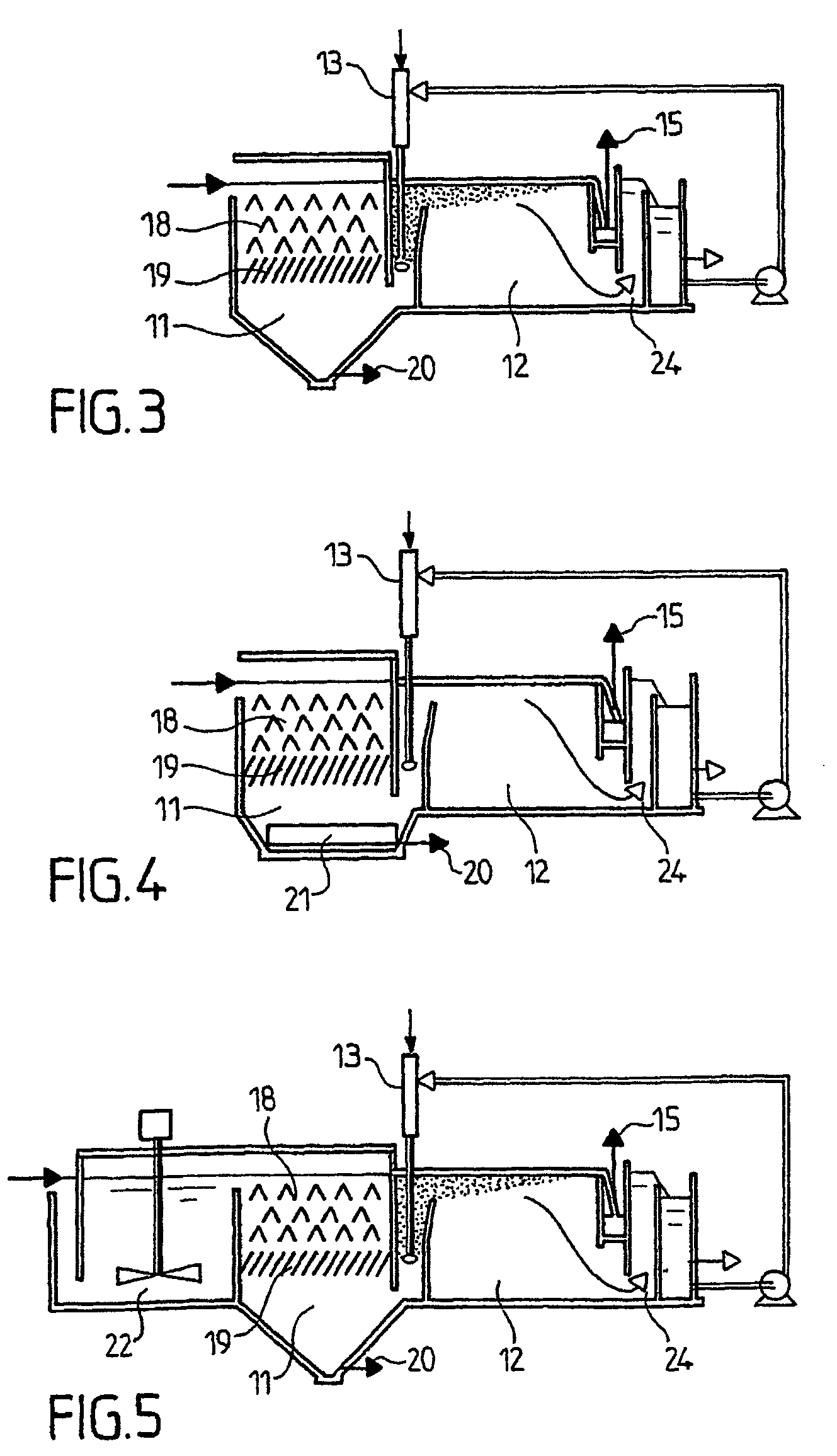
[0026]As may be understood, the basic idea of the present invention is to achieve the final flocculation step in the form of a downflow static flocculation zone, to provide below this a primary separation equipped with a removal of the heavier particles, the whole being positioned upstream of the actual flotation zone: under these conditions, the flotation cell only operates on the light particles, which it easily removes.

Problems solved by technology

The weak point of flotation is that the microbubbles stick with difficulty to the mineral particles and cannot guarantee that the heavy particles present in the water will rise to the surface.
Accordingly, the applications of flotation are often limited to the clarification of relatively uncontaminated waters, particularly lake waters, wells, seawater and specific industrial effluents or wash waters from biological filters.
Despite their advantages, flotation units have hardly been able to compete with the generation of high-speed lamellar settlers, with sludge bed or ballast, particularly for the following reasons:generally oversized volume of the flocculation zone;relatively low separation rates;pressurization energy cost andrelatively limited field of application.
By contrast, the major drawback of flotation is that this technique cannot extend its field of application to the vast field of river waters, wastewaters (primary, rainfall, etc.), wash waters, etc. due to the difficulty, indeed the impossibility, of “floating” dense and / or large-sized particles.
However, the results obtained are very mediocre, both in terms of operating cost and treatment quality.
The major drawback of this type of flocculation by mechanical stirring is that it imposes bulky flocculators and “inflates” the residence times of the effluent to be treated in the installation.

Method used


Image

  • Method and device for clarification of liquids, particularly water, loaded with material in suspension
  • Method and device for clarification of liquids, particularly water, loaded with material in suspension
  • Method and device for clarification of liquids, particularly water, loaded with material in suspension

Examples


Embodiment Construction

[0031]FIG. 1 shows the flocculator 11 and the flotation unit 12 with its surface scraper 14. According to the invention, a static flocculator with deflectors 18, under which a lamellar settling module 19 is placed, is positioned upstream of the flotation unit 12. The combination of the flocculator 18 and the lamellar settling module 19 constitutes the zone of downflow static flocculation—primary separation of heavier particles, said particles being removed at 20 in the bottom portion of this zone.

[0032]Thanks to this arrangement, the invention can be used to treat most types of waters, including those containing particles that are too light to settle and too heavy to float.

[0033]The lamellar settling module stage 19 situated under the baffles or deflectors of the static flocculator 18, in addition to the settling of the heavier particles, performs two supplementary functions:[0034]by increasing the number of deposition surfaces, it serves to retain particles of which the settling ra...


PUM

PropertyMeasurementUnit
Energyaaaaaaaaaa
Flocculationaaaaaaaaaa

Abstract

A method is disclosed for clarifying, by flotation, waters contaminated with suspended matter, wherein the clarification treatment takes place in two successive steps implemented in a single installation. The method principally involves flowing contaminated water through a downflow static flocculation step and then down through a lamellar settler separation step positioned directly below the downflow static flocculation step, the settling rates of the heavier particles of the lamellar settler separation step removing heavier particles from the water retained during the static flocculation / lamellar separation step being less than or equal to the settling rates of the floatable particles. The water which has passed through the static flocculation / lamellar settler separation step is then subjected to a flotation step which removes the light particles in the water of which the settling rate is lower than a flotation cutoff threshold.

Description

FIELD OF THE INVENTION[0001]The present invention relates to improvements made to methods, in particular physicochemical, for clarifying, by flotation, waters containing suspended matter.BACKGROUND OF THE INVENTION[0002]Flotation is a clarification technology (solid-liquid separation) which offers an alternative to settling, at least for certain types of water.[0003]According to this known technology (see in particular “Memento Technique de l'Eau” 1989, Volume 1, pages 171 et seq.), after a coagulation-flocculation step, the water is mixed with a “milk” (that is, an emulsion) of microbubbles, generally of air, the average diameter of which is between 40 and 80 microns. These microbubbles stick to the flocs which, thereby lightened, tend to rise to the surface of the flotation cell, where they accumulate to form a sludge layer or bed. The sludges are collected at the surface of the flotation unit, while the clarified water is removed via the bottom of the apparatus.[0004]A portion of...

Claims


Application Information

Patent Timeline
IPC IPC(8): C02F9/02C02F9/04C02F1/24C02F1/52B01D21/04B03D1/14B03D1/24B03D3/02
CPCB01D21/04B01D21/08B01D21/2433B01D21/245B03D3/02C02F1/24C02F1/52B03D1/1412B03D1/1481B03D1/247B01D21/0045B01D21/0042B03D3/06B03D1/14
Inventor VION, PATRICK
Owner ONDEO DEGREMONT INC
Learn More