

System and method for thermally controlling an electronic display with reduced noise emissions
a technology of electronic display and noise emission, applied in the field of cooling systems, can solve the problems of increasing the difficulty of cooling the internal display components, increasing the cost of cooling,
- Summary
- Abstract
- Description
- Claims
- Application Information
AI Technical Summary
Benefits of technology
Problems solved by technology
Method used
Image

Examples
Embodiment Construction
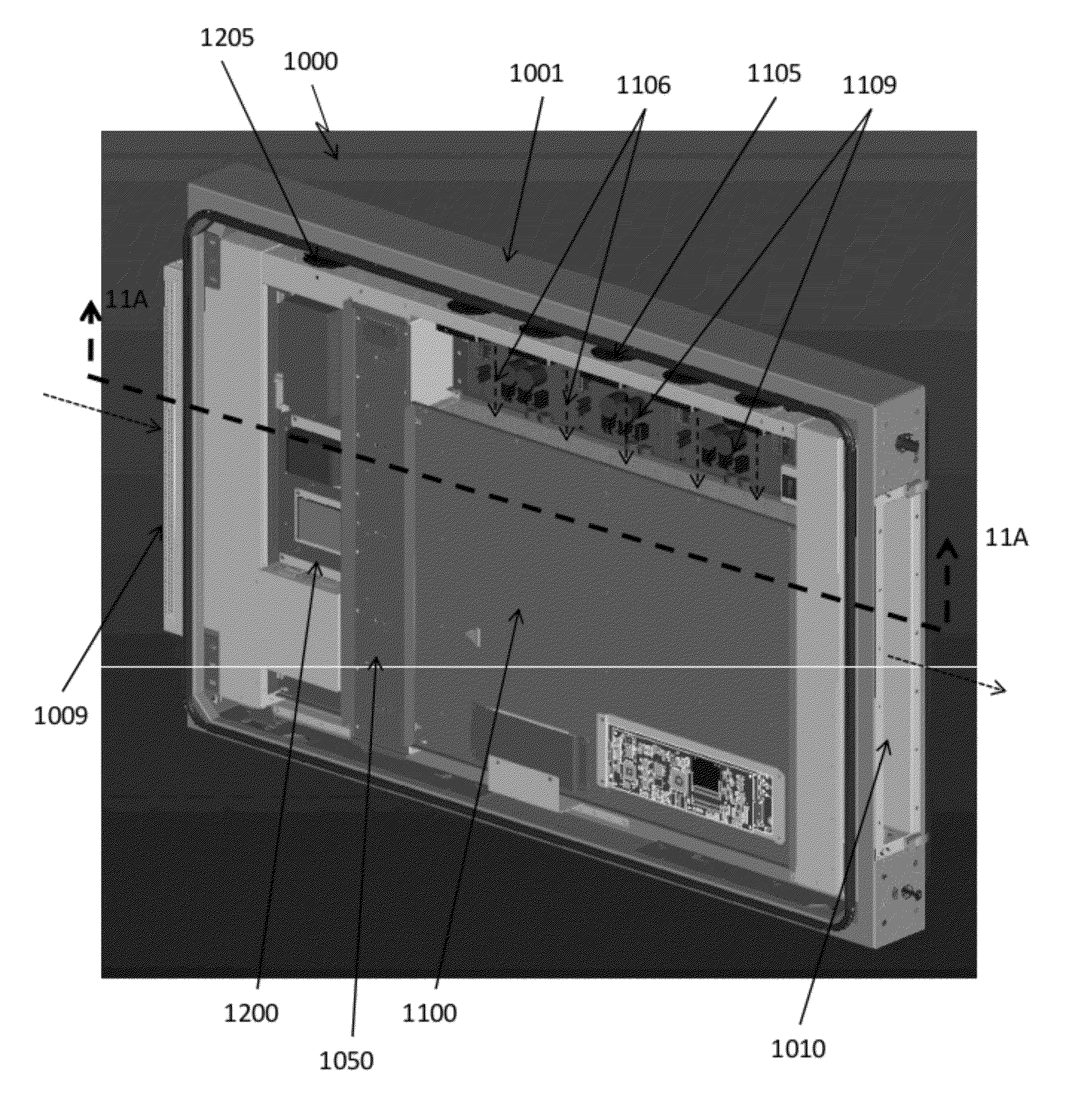
[0008]Exemplary embodiments may use a combination of circulating gas and ambient gas in order to adequately cool an electronic display. Circulating gas may be used to remove heat from the front of the image assembly. Circulating gas may also be used to remove heat from internal electronic assemblies. When using a LCD as the electronic image assembly, circulating gas may also be used to remove heat from the backlight cavity of the LCD. Because the gas is only circulating within the display, it can remain free of particulate and contaminates and will not harm the display.
[0009]Ambient gas may be ingested into the display in order to cool the circulating gas. The ambient gas and the circulating gas may be drawn through a heat exchanger which will allow the heat to transfer from the circulating gas to the ambient gas, preferably without letting the ambient and circulating gases mix with one another. An exemplary embodiment would use a cross-flow heat exchanger. An additional flow of amb...
PUM
 Abstract
Description
Claims
Application Information