Damper device

a technology of adamant device and a ring, which is applied in the direction of fluid gearing, coupling, gearing, etc., to achieve the effect of reducing the transmission of vibration and relatively low torque of the motor

Active Publication Date: 2012-08-16
AISIN AW CO LTD
View PDF4 Cites 18 Cited by
  • Summary
  • Abstract
  • Description
  • Claims
  • Application Information

AI Technical Summary

Benefits of technology

[0005]Then, it is a main object of the present invention to reduce the influence of the resonance of a plurality of intermediate elements included in a damper device.
[0008]The damper device includes the input element to which power is transmitted from the motor, the first intermediate element to which power is transmitted from the input element via the first elastic body, the second intermediate element to which power is transmitted from the first intermediate element via the second elastic body, and the output element to which power is transmitted from the second intermediate element via the third elastic body. Then, in this damper device, the stiffness of the third elastic body is set so as to be higher than the stiffness of the second elastic body. This makes it easy to substantially integrate the first intermediate element and the second intermediate element, and the resonance frequency of the first intermediate element and second intermediate element is increased by setting the stiffness of the third elastic body so as to be relatively high, so it is possible to cause resonance between the first intermediate element and the second intermediate element when the rotation speed of the input element is relatively high, that is, when the rotation speed of the motor is relatively high, and torque (vibrating force) from the motor is relatively low. As a result, an increase in the vibration level of the damper device as a whole (output element) due to resonance between the first intermediate element and the second intermediate element is suppressed to thereby make it possible to reduce transmission of relatively large vibrations to the downstream side of the damper device. Thus, in this damper device, it is possible to appropriately reduce the influence of the resonance of the plurality of intermediate elements.
[0009]Furthermore, a stiffness of the first elastic body may be lower than the stiffness of the second elastic body. By so doing, the stiffness of the third elastic body is set so as to be relatively high to increase the resonance frequency of the first intermediate element and second intermediate element and to decrease the resonance frequency of the damper device as a whole while the stiffness of the first elastic body is set so as to be low to thereby make it possible to improve the vibration damping characteristic of the damper device as a whole.
[0010]In addition, a stiffness of the first elastic body may be lower than the stiffness of the third elastic body and may be higher than or equal to the stiffness of the second elastic body. By so doing, it is possible to further increase the resonance frequency of the first intermediate element and second intermediate element, and to further decrease the resonance frequency of the damper device as a whole.
[0012]Then, the input element may be connected via a lock-up clutch to an input member coupled to the motor, and the output element may be coupled to an input shaft of a transmission. That is, the damper device is able to cause resonance between the first intermediate element and the second intermediate element or decrease the resonance frequency of the damper device as a whole when the rotation speed of the input element is relatively high, that is, when the rotation speed of the motor is relatively high, and torque (vibrating force) from the motor is relatively low. Thus, by using the above damper device, when the rotation speed of the motor is extremely low, it is possible to carry out lockup by the lock-up clutch, that is, couple the input member to the input shaft of the transmission, while appropriately reducing transmission of vibrations from the input member to the input shaft of the transmission.

Problems solved by technology

However, the above described Japanese Patent Application Publication No. 2001-82577 does not consider anything about the resonance of the plurality of intermediate elements.

Method used


Image

  • Damper device
  • Damper device
  • Damper device

Examples


Embodiment Construction

[0016]A mode for carrying out the present invention will now be described using an embodiment.

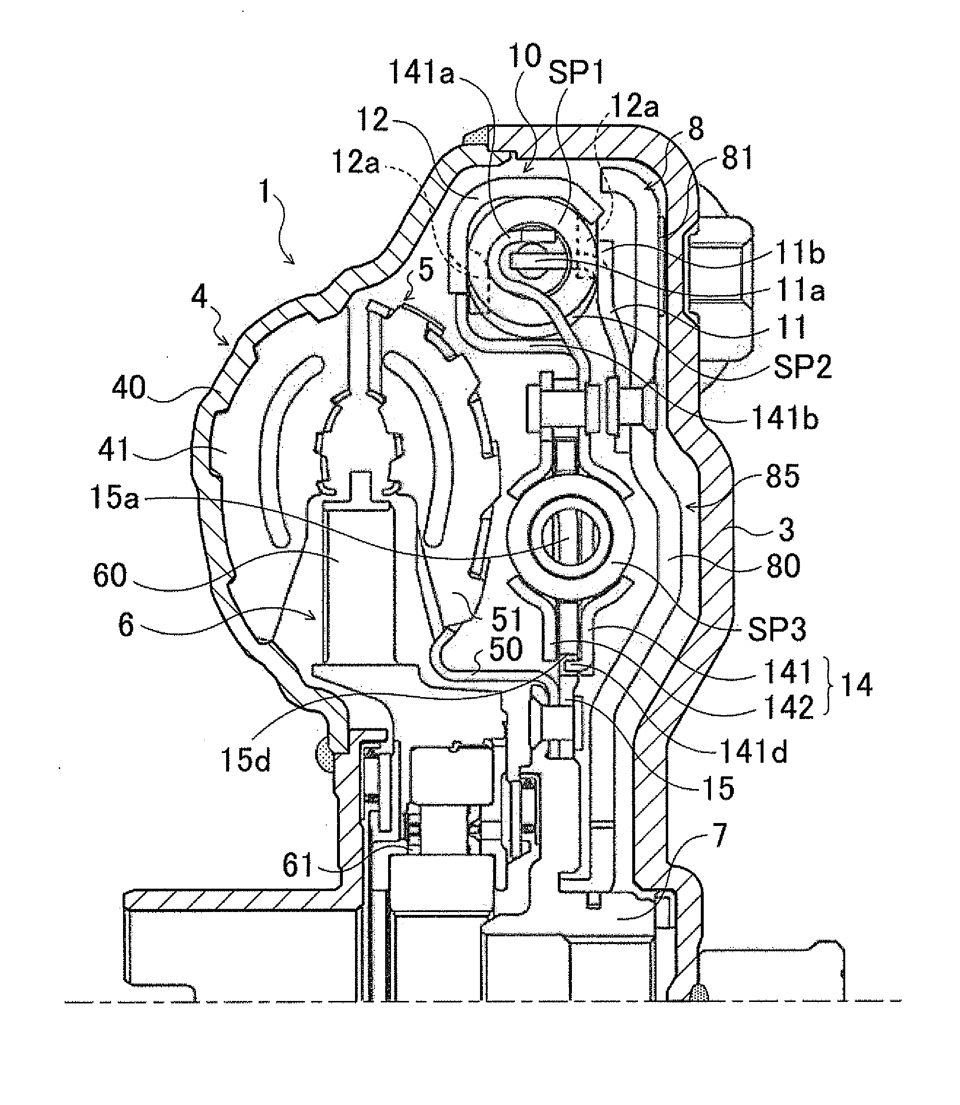
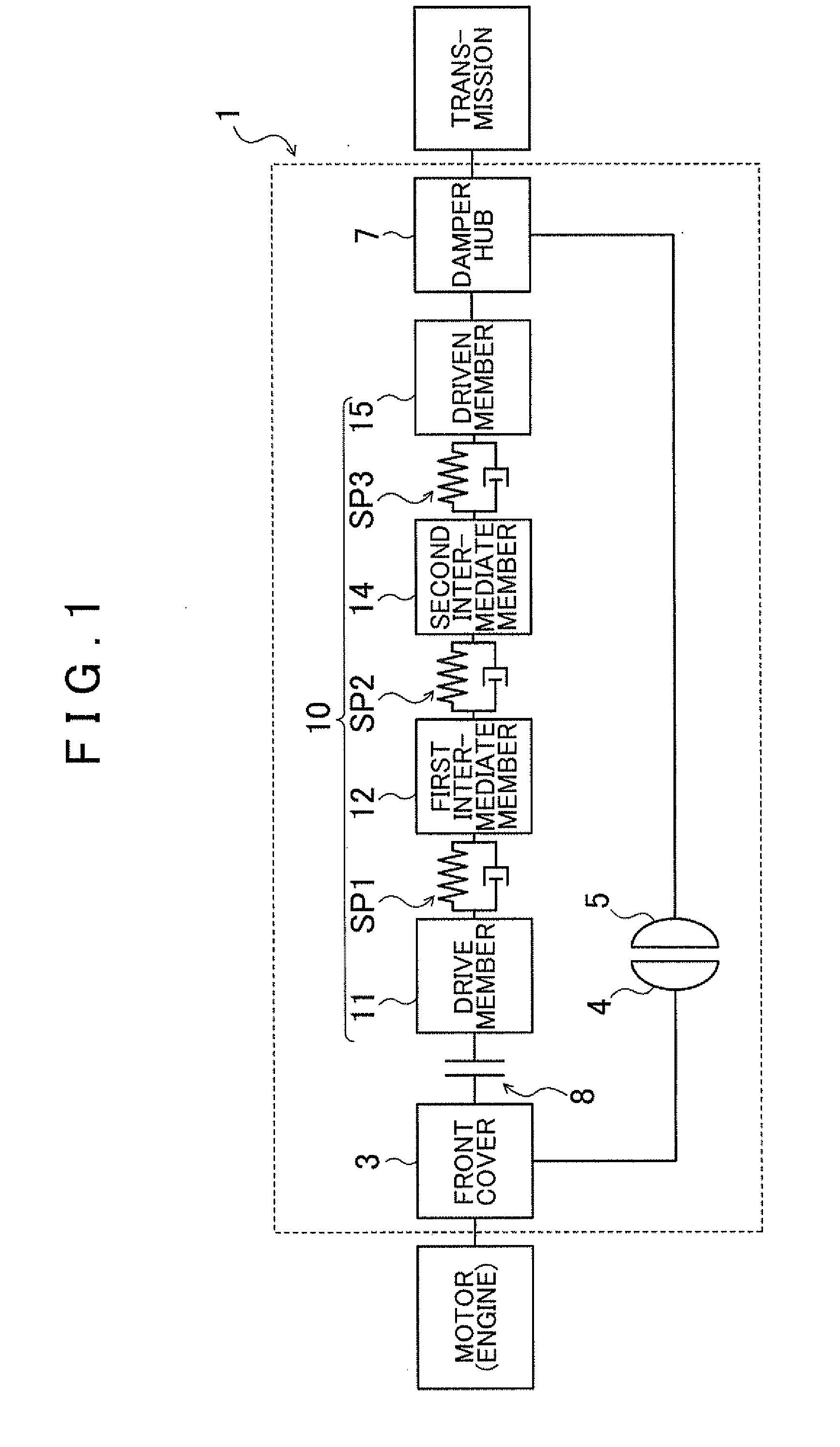
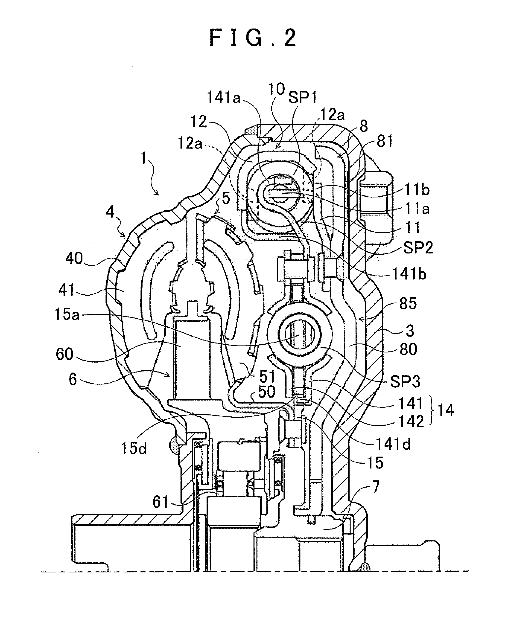
[0017]FIG. 1 is a schematic configuration diagram that shows a fluid transmission apparatus 1 that includes a damper device 10 according to an embodiment of the present invention. FIG. 2 is a partially cross-sectional view that shows the fluid transmission apparatus 1. The fluid transmission apparatus 1 shown in these drawings is a torque converter that is mounted as a starting apparatus on a vehicle equipped with an engine (internal combustion engine) that serves as a motor. The fluid transmission apparatus 1 includes: a front cover (input member) 3 that is coupled to a crankshaft of the engine (not shown); a pump impeller (input-side fluid transmitting element) 4 that is fixed to the front cover 3; a turbine runner (output-side fluid transmitting element) 5 that is rotatable coaxially with the pump impeller 4; a stator 6 that rectifies the flow of hydraulic oil (hydraulic fluid) from the ...


PUM


Abstract

A damper device including an input element to which power from a motor is transmitted; a first elastic body to which power is transmitted from the input element; a first intermediate element to which power is transmitted from the first elastic body; a second elastic body to which power is transmitted from the first intermediate element; a second intermediate element to which power is transmitted from the second elastic body; a third elastic body to which power is transmitted from the second intermediate element; and an output element to which power is transmitted from the third elastic body. A stiffness of the third elastic body is higher than a stiffness of the second elastic body.

Description

INCORPORATION BY REFERENCE[0001]The disclosure of Japanese Patent Application No. 2011-029716 filed on Feb. 15, 2011 including the specification, drawings and abstract is incorporated herein by reference in its entirety.BACKGROUND OF THE INVENTION[0002]The present invention relates to a damper device that includes an input element to which power is transmitted from a motor, a first intermediate element to which power is transmitted from the input element via a first elastic body, a second intermediate element to which power is transmitted from the first intermediate element via a second elastic body, and an output element to which power is transmitted from the second intermediate element via a third elastic body.DESCRIPTION OF THE RELATED ART[0003]There is known an existing damper device of this type, which includes first elastic members that are provided on a piston of a lock-up device, second elastic members that are provided on a driven plate fixed to a turbine runner of a torque...

Claims


Application Information

Patent Timeline
Patent Type & Authority Applications(United States)
IPC IPC(8): F16D3/66F16F15/123
CPCF16H45/02F16H2045/0294F16H2045/0231F16H2045/0205
Inventor TAKIKAWA, YOSHIHIROOI, YOICHI
Owner AISIN AW CO LTD
Why Eureka
Try Eureka