Gas-powered tool motor

a tool motor and gas-powered technology, applied in the field of linear motors, can solve the problems of reducing charging and discharging efficiency, bypass valves add to the design complexity of linear motors,

Active Publication Date: 2012-08-23
ADAMS JOSEPH S
View PDF6 Cites 27 Cited by
  • Summary
  • Abstract
  • Description
  • Claims
  • Application Information

AI Technical Summary

Benefits of technology

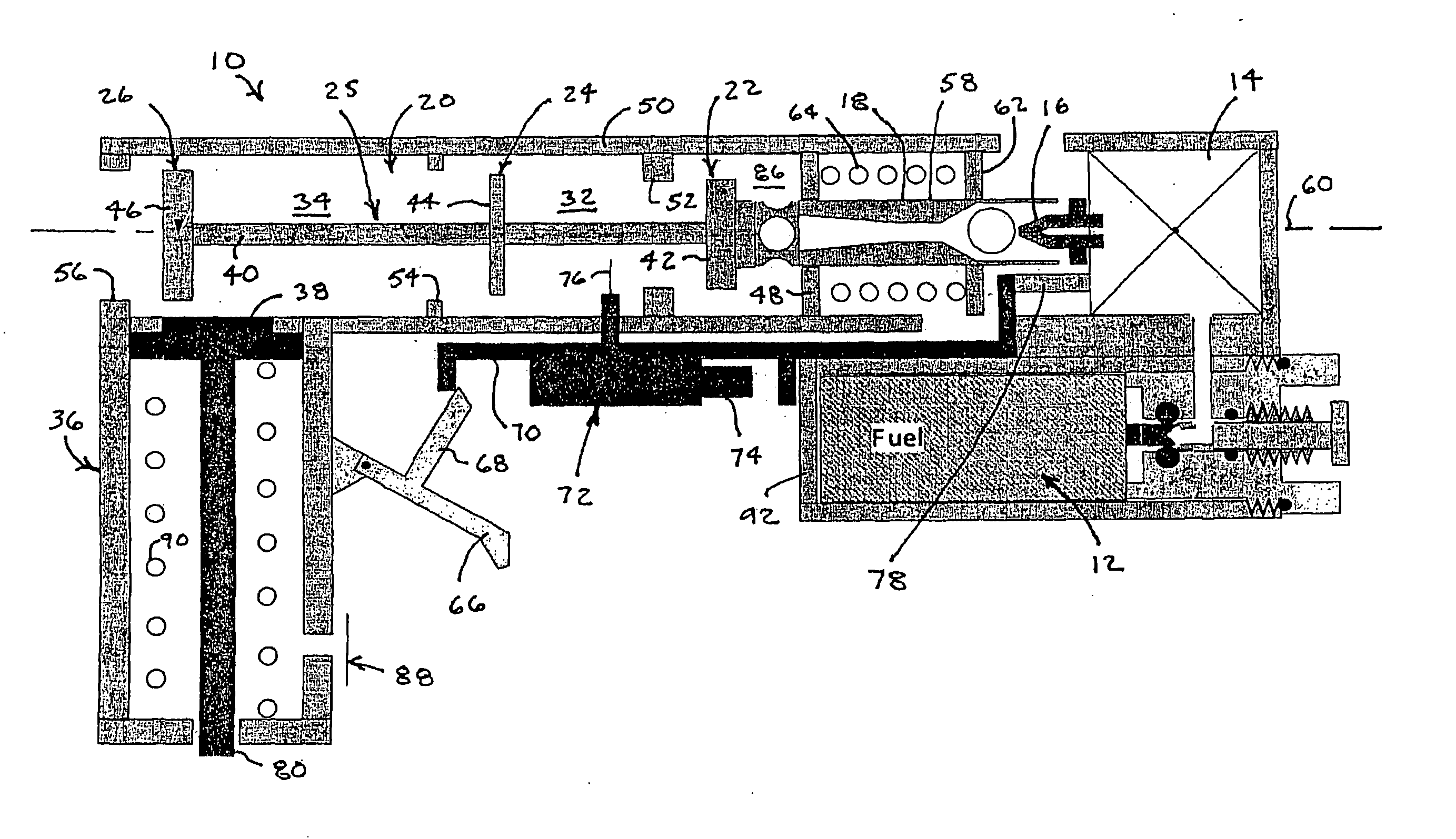
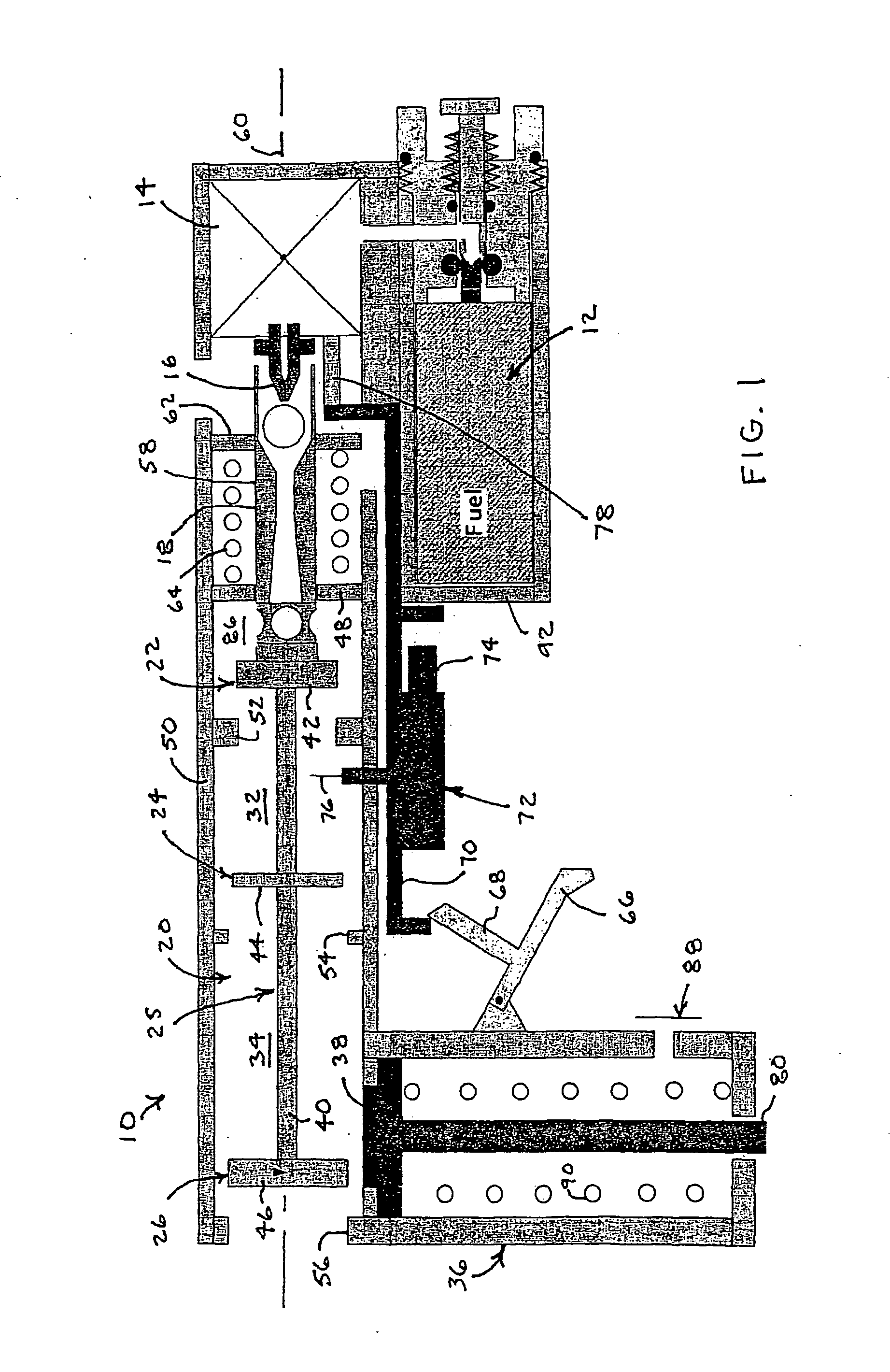
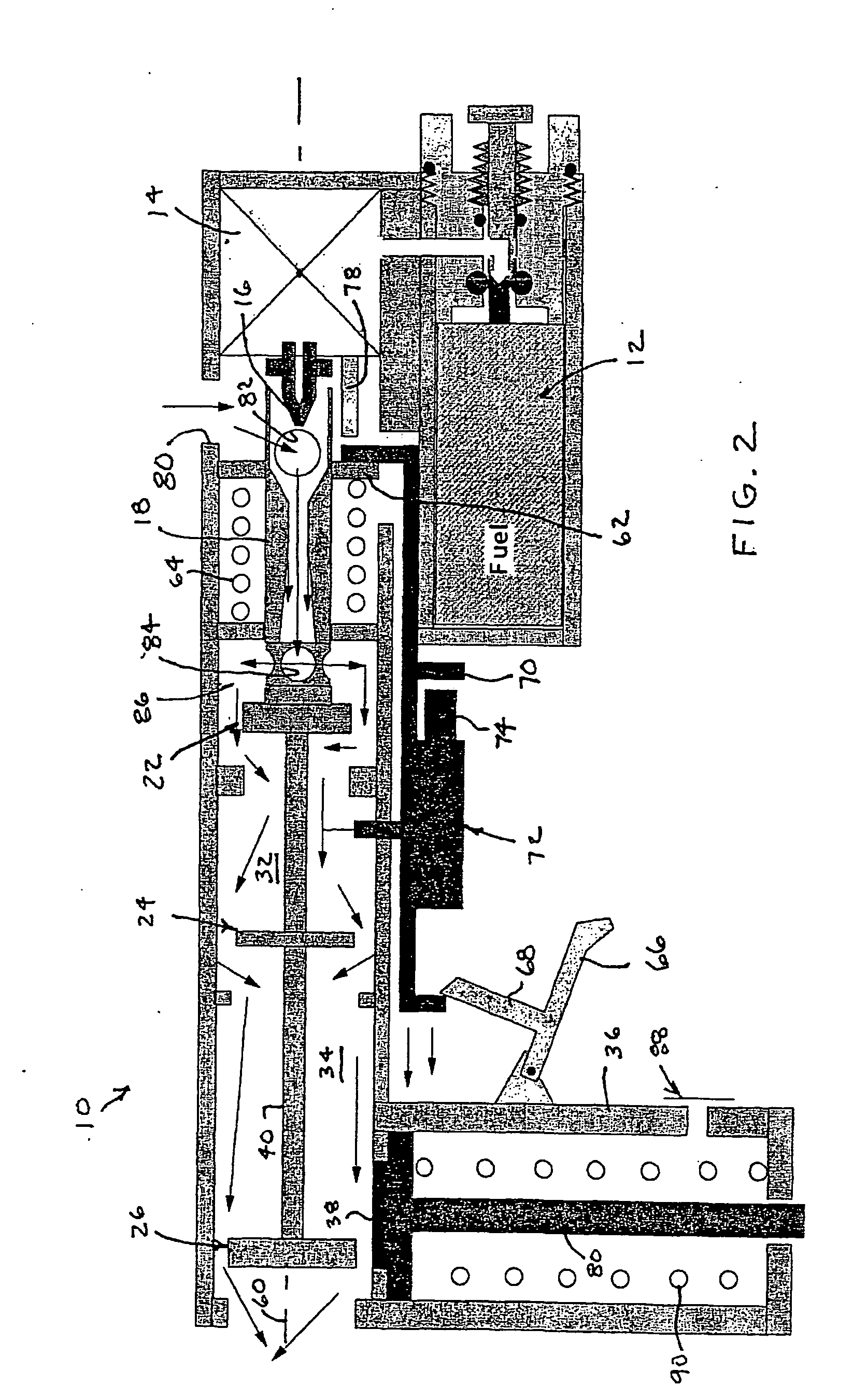
[0009]Among its preferred embodiments, the invention features an integrated valving and combustion control system, which facilitates the operation of gas-powered hand tools with two-stage combustion chambers such as may be used to drive fasteners, launch projectiles, or perform other useful work. A common mechanical tie links operations of an intake valve for regulating the intake of gases into a pre-combustion chamber and an exhaust valve for regulating the discharge of gases from a main combustion chamber. A control plate limits the flow of gases between the two combustion chambers. Building upon the common mechanical linkage, which allows for the intake and exhaust valves to be operated in tandem, the cost and complexity of the control system can be reduced, the reliability of the control system can be increased, and better control can be provided for matching output force to tool specifications.
[0012]The control plate can be connected to the tie and moved together with the intake and exhaust closure members along the common axis or the control plate can be fixed to the housing with the tie passing through the control plate. Particularly for higher power applications, the control plate is preferably formed at least in part by a control closure member of a control valve. The tie moves the control closure member together with the intake and exhaust closure members along the common axis for opening and closing the intake, control and exhaust valves. The control valve that has an open position and a closed position. In the closed position, the control valve supports the limited flows between the pre-combustion combustion chamber and the main combustion chamber. In the open position, the control valve supports less restricted flows of air from the pre-combustion chamber to the main combustion chamber. The less restrictive flows of air supported by the open position of the control valve obviate the need for a conventional bypass valve.
[0015]The open position of the control valve obviates the need for a bypass valve since the open position of the control valve allows for a more nearly free flow of gases between the pre-combustion and combustion chambers. The closed position of the valve still functions as a control plate between the pre-combustion and combustion chambers to support a desired two-stage combustion process.
[0017]Alternatively, a solenoid, a fluid-power actuator, or other controllable power source, can be connected (directly or indirectly) to the tie between closure members for collectively opening or closing the intake, control, and exhaust valves. The solenoid, which can be separately powered by battery, can be electrically connected to the trigger for timing its operation. The fluid-powered actuator, which can be powered by combustion gases or fuel pressure, can be connected to fluid timing devices as well as the trigger for timing its operation. Automatic or manual operation of the gas-powered tool can be achieved.
[0022]For purposes of thermal regulation, a fuel supply, which is preferably stored as a liquefied gas under pressure, can be placed in thermal communication with the combustion chamber. For example, both the fuel supply and the combustion chamber can be arranged within thermally conductive housings, and the two thermally conductive housings can be brought into contact so that the fuel supply functions as a heat sink for the combustion chamber. Under cold ambient conditions, heating the fuel can itself be advantageous.

Problems solved by technology

The bypass valves add to the design complexity of linear motors by requiring the opening and closing of the bypass valve in response to different stages in the combustion cycle of the motor including recharging (open), detonating (closed), and discharging (open).
Limited orifices through control walls, whether regulated by check valves or not, tend to impose restrictions on the free flow of gasses between the chambers and can result in reduced charging and discharging efficiencies.

Method used


Image

  • Gas-powered tool motor
  • Gas-powered tool motor
  • Gas-powered tool motor

Examples


Embodiment Construction

[0048]A gas-powered tool motor 10, such as might be used for driving fasteners, appears within FIGS. 1-4 in various stages of operation. Beginning at a dormant state shown in FIG. 1, the tool motor 10 includes a regulated fuel supply 12 and a fuel injector 14 for injecting a metered amount of fuel through a nozzle 16 into an air-drafting jet pump 18 for delivering a mixture of fuel and air into a compound combustion chamber 20. The mixture of fuel and air enters the compound combustion chamber 20 through an intake valve 22 and spent exhaust gases exit the compound combustion chamber 20 through an exhaust valve 26. A control valve 24 divides the compound combustion chamber 20 into a pre-combustion chamber 32 and a main combustion chamber 34.

[0049]The compound combustion chamber 20 is preferably housed in the handle (not shown) of a tool. A cylinder 36 containing a displaceable power piston 38 is preferably oriented at a right angle or other orientation with respect to the compound co...


PUM


Abstract

A gas-powered tool motor includes a combustion chamber with an intake valve at one end, an exhaust valve at another end, and a control plate or control valve between two portions of the combustion chamber. A piston or other positive displacement device is in communication with the combustion chamber. The intake and exhaust valves have closure members that are movable along a common axis in tandem between collective open positions for recharging the combustion chamber with the fuel and air mixture and collective closed positions for detonating the fuel and air mixture in the combustion chamber and displacing the positive displacement device. The control plate or control valve supports limited air flows from a first portion of the combustion chamber to a second portion of the combustion chamber even in the closed position of the control valve for supporting two-stage combustion.

Description

CROSS-REFERENCE TO RELATED APPLICATIONS[0001]This application is a non-provisional application claiming domestic priority to U.S. Provisional Application No. 61 / 254,275 filed on Oct. 23, 2009 and U.S. Provisional Application No. 61 / 347,052 filed on May 21, 2010. Both identified provisional applications are hereby incorporated by reference.TECHNICAL FIELD[0002]The invention relates to linear motors, particularly for use in gas-powered tools such as for driving fasteners, launching projectiles, or performing other useful work, and to combustion systems for such motors and associated controls.BACKGROUND[0003]Some gas-powered tools with spark-ignitions have two part combustion chambers: a pre-combustion chamber and a main combustion chamber. Ignition originates in the pre-combustion chamber. Some unburned fuel and air in the pre-combustion chamber is forced ahead of a flame jet into the main combustion chamber. Upon arrival, the flame jet triggers combustion of a compressed fuel and air...

Claims


Application Information

Patent Timeline
Patent Type & Authority Applications(United States)
IPC IPC(8): F02B19/00F02B63/02F02D29/00F01L1/26F01L1/36
CPCF01B11/007F02B19/14F01L2003/25B23Q5/033Y02T10/125F02B63/02F02B19/1028B25C1/08Y02T10/12
Inventor ADAMS, JOSEPH S.
Owner ADAMS JOSEPH S
Why Eureka
Try Eureka