
Balloon Holder Caddy Systems

a balloon holder and caddy technology, applied in the field of balloon holder/caddy system, can solve the problems of unsatisfactory, unsatisfactory, expensive and time-consuming,

Inactive Publication Date: 2012-08-23
PARELLO JAMES +1
View PDF6 Cites 15 Cited by
  • Summary
  • Abstract
  • Description
  • Claims
  • Application Information

AI Technical Summary

Benefits of technology

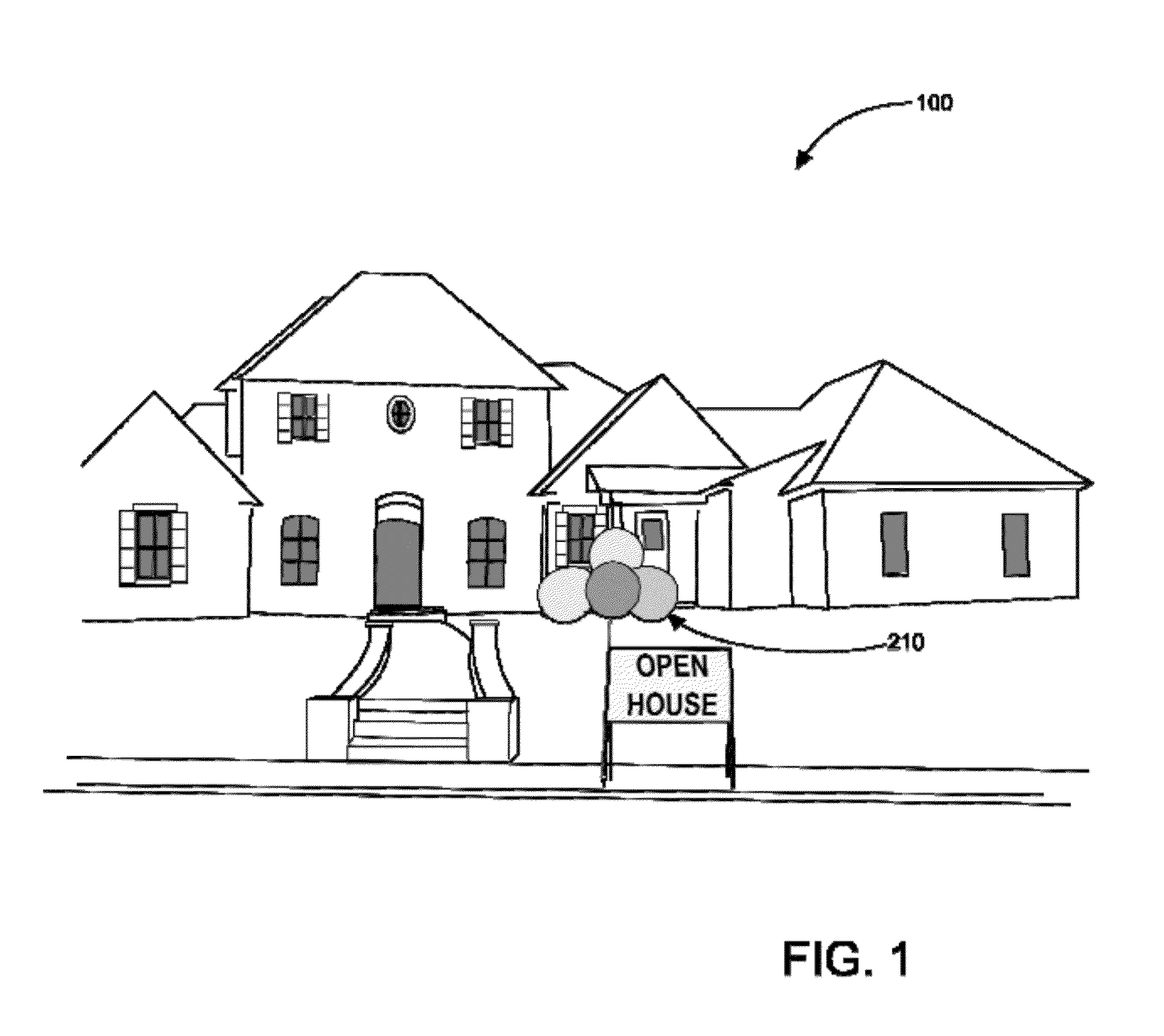
[0012]In view of the foregoing disadvantages inherent in the known balloon holder art, the present invention provides a novel balloon holder caddy system. The general purpose of the present invention, which will be described subsequently in greater detail, is to simulate the aesthetic appearance of helium filled balloons yet avoiding the expenses, and associated safety hazards.
[0013]Balloon holder caddy system can aerially support balloons and attach them to signs and various objects to signify parties, sales to any and all items, real estate showings, yard sales, reunions, and other events. The device effectively eliminates the need for helium balloons, as it can stabilize regular balloons in the air above a sign or object. By using this device, individuals can save time and money by purchasing regular balloons as opposed to helium balloons, but will not have to sacrifice their aesthetically pleasing appeal. Real estate agents or individuals who use balloons to decorate signs for various events will appreciate the convenience and appeal that this product affords, as it calls attention to such signs or events.
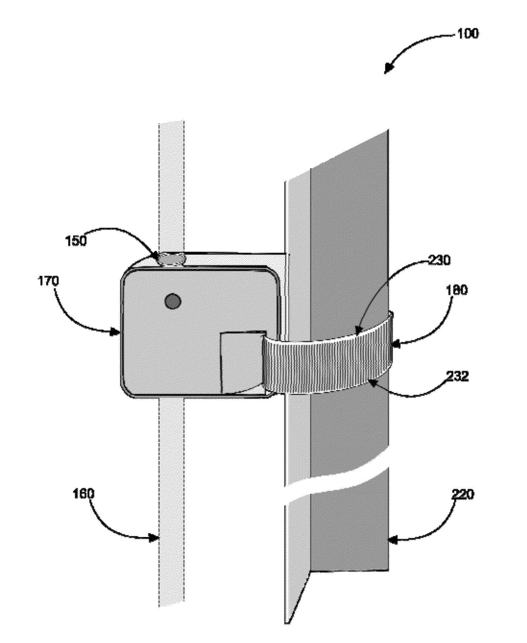
[0017]The rod in preferred embodiments is about 4 feet long and about ¼ inch in diameter and may comprise fiberglass in the preferred embodiment, but may comprise other materials such as plastic or other suitable equivalent in other embodiments. The rod is flexible in certain embodiments and rigid in other embodiments. The intermediate leg gripper and the base leg gripper comprise a rectangular through-hole such that the first re-useable fastener and the second re-useable fastener respectively are able to pass therethrough to secure the intermediate leg gripper and the base leg gripper to a common sign-post leg. The base leg gripper comprises a receiver, the third rod aperture, for receiving the rod which has an interference fit with the distal end of the rod such that the rod is able to be push-inserted into the third rod aperture in the upper-side of the base leg gripper so that the rod and the base leg gripper are removably attached.
[0018]The base leg gripper, in a preferred embodiment, is removably attachable to a vertical column such as a sign post leg or other structure via the second re-useable fastener. An alternate embodiment may comprise a chair leg bracket for displaying balloons vertically. The base leg gripper, the intermediate leg gripper, and the top gang-clip also may comprise plastic in a preferred embodiment. The balloon holder caddy system is usable to removably attach at least one balloon to the top gang-clip via at least one balloon slot. The rod is able to be removably attached to the sign post leg via the intermediate leg gripper and the base leg gripper such that the balloon holder caddy system is usable to display balloon(s).

Problems solved by technology

This can be expensive and time consuming, especially for real estate agents who may add balloons to their signs.
Additionally, when setting up signs, a helium-filled balloon could potentially float away, leaving individuals without their full display.
Individuals may tape stick balloons to displays, however this may not be ideal.
These cylinders are very heavy and when purchased, can only be stored in a convenient and safe location, and the balloons brought to the container to be filled.
It may be impractical to move a Helium cylinder around from location to location to fill balloons.
While Helium-filled balloons are associated with parties and happiness, the heavy weight of Helium cylinders has been responsible for many back lifting injuries.
Vision can become completely obstructed by floating balloons that get loose.

Method used


Image

  • Balloon Holder Caddy Systems
  • Balloon Holder Caddy Systems
  • Balloon Holder Caddy Systems

Examples


Embodiment Construction

[0028]As discussed above, embodiments of the present invention relate to a balloon holder device and more particularly to a balloon holder caddy system as used to simulate helium-filled balloons, reducing wasted time, reducing environmental pollution and improving the associated safety issues, yet providing an aesthetically-pleasing display means.

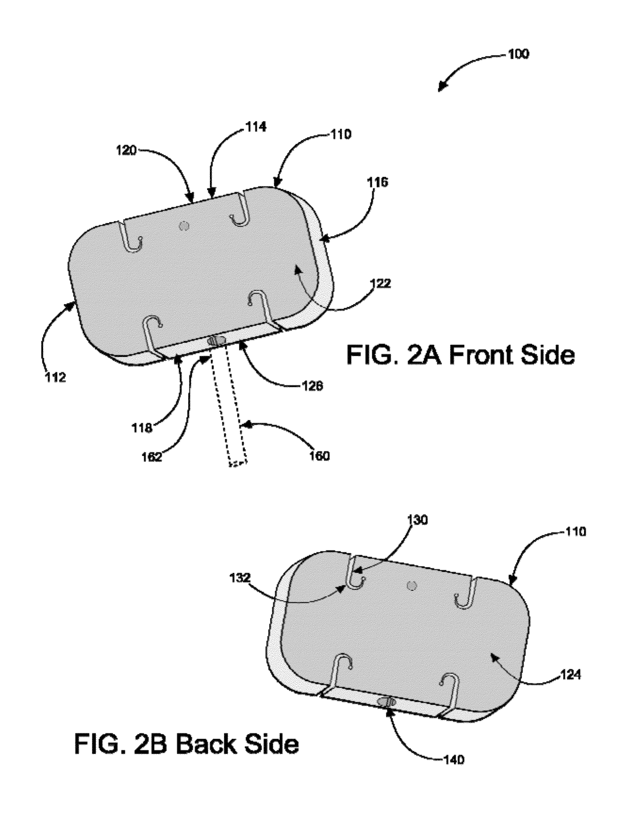
[0029]Generally speaking, a balloon holder caddy system allows individuals to use regular balloons, as opposed to helium-filled balloons, to decorate signs for real estate showings, parties, and other events. Balloon holder caddy system can comprise a small rectangular base that can be made from hard plastic with a drilled hole. There can be a second smaller hole in the base, partially drilled, measuring approximately ¼″ in diameter. Inserted into this hole can be a fiberglass rod ranging from 2′ to 10′ long. Attached to the top of the fiberglass rod can be a square, hard piece of plastic with four “J” shape slits and four small holes. To u...


PUM


Abstract

A balloon holder caddy system designed to simulate the look of Helium-filled balloons, to reduce the safety hazards associated with traveling with Helium-filled balloons in the passenger compartment of an automobile, and to eliminate repeated trips to a base location and back (a product use location such as is common with real estate agent's sign postings.) Balloon holder caddy system comprises a top gang-clip with multiple balloon neck receiving slots for creating a balloon cluster, a rod for elevating the balloon cluster simulating helium filled balloons, and an intermediate leg gripper and a base gripper for attaching to a sign-post leg using re-useable / releasable zip-ties. The system providing a unique and efficient balloon displaying means.

Description

CROSS-REFERENCE TO RELATED APPLICATION[0001]The present application is related to and claims priority from prior provisional application Ser. No. 61 / 443,789, filed Feb. 17, 2011 which application is incorporated herein by reference.COPYRIGHT NOTICE[0002]A portion of the disclosure of this patent document contains material which is subject to copyright protection. The copyright owner has no objection to the facsimile reproduction by anyone of the patent document or the patent disclosure, as it appears in the Patent and Trademark Office patent file or records, but otherwise reserves all copyright rights whatsoever. 37 CFR 1.71(d).BACKGROUND OF THE INVENTION[0003]The following includes information that may be useful in understanding the present invention(s). It is not an admission that any of the information provided herein is prior art, or material, to the presently described or claimed inventions, or that any publication or document that is specifically or implicitly referenced is pr...

Claims


Application Information

Patent Timeline
IPC IPC(8): F16M13/00
CPCA63H27/10Y10T24/15A63H2027/1041
Inventor PARELLO, JR., JAMESPARELLO, DALE
Owner PARELLO JAMES
Learn More