Ultra-low voltage coefficient capacitors

a capacitor and low voltage technology, applied in the field of capacitors, can solve the problems of insufficient vcc and capacitive charge distribution precision of prior art integrated circuit capacitors in a circui

Active Publication Date: 2012-08-23
X FAB SEMICON FOUNDRIES
View PDF4 Cites 44 Cited by
  • Summary
  • Abstract
  • Description
  • Claims
  • Application Information

AI Technical Summary

Problems solved by technology

However, prior art integrated circuit capacitors have not been satisfactory in

Method used


Image

  • Ultra-low voltage coefficient capacitors
  • Ultra-low voltage coefficient capacitors
  • Ultra-low voltage coefficient capacitors

Examples


Embodiment Construction

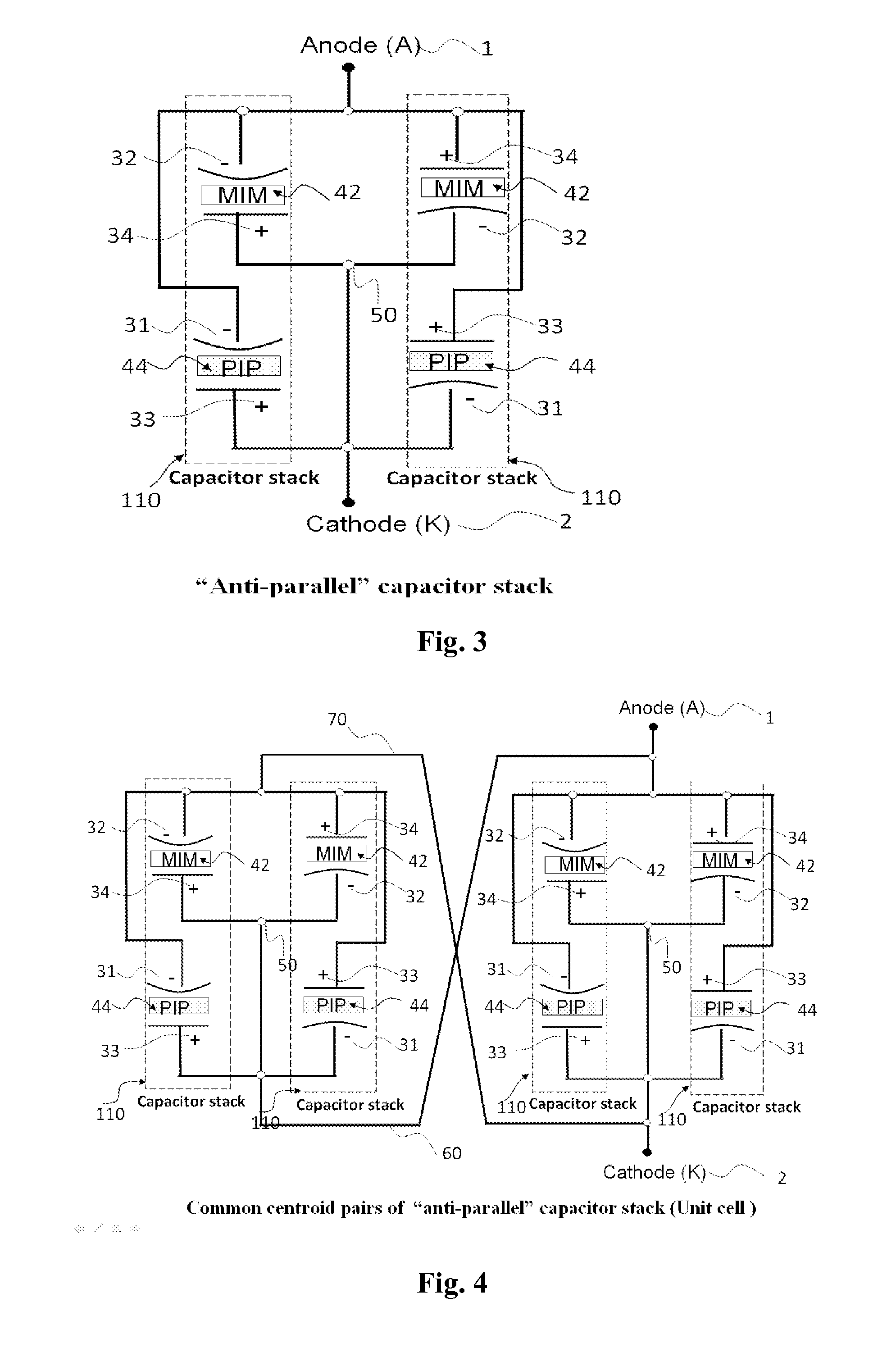
[0028]Embodiments may use a combination of capacitor types to form a composite capacitor array which demonstrates a minimal capacitance change with applied voltage. The voltage dependent behaviour is numerically described by Voltage Coefficient of Capacitance (VCC) values. The present invention relates to a novel technique which allows these special low voltage coefficient devices to be created by using a common centroid pair of “anti-parallel 60 and 70” capacitors configured in a tessellated pattern. Arranging the capacitors about a “centroid” point reduces the effect of variations in properties across the wafer. Any variations tend to be cancelled out as a result of the common centroid arrangement of the components. Through a combination of capacitor types and layout style it is possible to engineer a cost-effective, ultra-low voltage coefficient solution on mainstream CMOS processes technologies. The same techniques could be employed on other process technologies: eg. bipolar, Bi...


PUM


Abstract

A capacitor has first and second conducting plates and a dielectric region between the plates, wherein the dielectric region comprises two dielectric materials for each of which the variation of capacitance with voltage can be approximated by a polynomial having a linear coefficient and a quadratic coefficient, and wherein the quadratic coefficients of the two dielectric materials are of opposite sign. The capacitor comprises for example a first capacitor (42) and a second capacitor (44) that one connected in an anti-parallel manner. The insulating layer (18) of the first capacitor comprises silicon nitride and the insulating layer (16) of the second capacitor comprises silicon dioxide

Description

TECHNICAL FIELD[0001]The invention relates to capacitors having improved voltage coefficients, and particularly, although not exclusively, to integrated circuit dielectric capacitors used within mixed signal application circuits such as a Polysilicon-Insulator-Polysilicon (PIP) capacitor, a Metal-Insulator-Metal (MIM) capacitor etc.BACKGROUND[0002]The following prior art documents relate to the background to this invention:[0003]1. Patent WO2009013533: MIM capacitor structure and methods of manufacturing the same.[0004]2. U.S. Pat. No. 4,878,151: Anti-parallel capacitor.[0005]3. U.S. Pat. No. 4,918,454: Compensated capacitors for switched capacitor input of an analog-to-digital converter.[0006]4. U.S. Pat. No. 6,404,376: Capacitor array having reduced voltage coefficient induced non-linearities.[0007]5. US Patent No. 2007200162: Reducing dielectric constant for MIM capacitor[0008]6. US Patent No. 2004209423: Methods for reducing capacitor dielectric absorption and voltage coefficien...

Claims


Application Information

Patent Timeline
IPC IPC(8): H01L29/92
CPCH01G4/08H01G4/20H01L28/40H01L27/0688H01L27/0805H01L27/0207
Inventor STRIBLEY, PAUL RONALDKONG, SOON TATVERITY, DAVID JOHN
Owner X FAB SEMICON FOUNDRIES
Why Eureka
Try Eureka