Radio communication method, radio communication system, and radio transmission apparatus

a radio communication system and radio transmission technology, applied in the direction of multiplex communication, orthogonal multiplex, wireless communication, etc., can solve problems such as widespread interference, and achieve the effect of minimizing degradation of characteristics and flexible communication

Inactive Publication Date: 2012-08-23
SHARP KK
View PDF11 Cites 22 Cited by
  • Summary
  • Abstract
  • Description
  • Claims
  • Application Information

AI Technical Summary

Benefits of technology

[0026]For a terminal that requires high transmission power, communication can be performed without distortion of signals by using rotation orthogonal codes and transmitting data with a high SF. By changing SF in accordance with required transmission power, more flexible communication can be realized while minimizing degradation in characteristics that results from communication being performed in a wide frequency band.

Problems solved by technology

High peak power is not a very large problem in downlink communication which has a relatively large margin in transmission power amplification capability, but can be a significant issue in uplink (i.e., communication from a mobile station to the base station apparatus) which has no margin in transmission power amplification capability.
It is said that in generation of CDM-OFDM signals, use of orthogonal codes enables data to be demultiplexed, ideally on a receiver, and use of scrambling codes specific to the base station can spread interference as well.

Method used


Image

  • Radio communication method, radio communication system, and radio transmission apparatus
  • Radio communication method, radio communication system, and radio transmission apparatus
  • Radio communication method, radio communication system, and radio transmission apparatus

Examples


first embodiment

[0084]Since the present invention performs spreading in frequency domain but sets data efficiency to 1, it cannot spread effect when an interference signal has a similar signal form, which leads to degradation in communication quality. This is because correlation becomes high due to use of the same spreading code in all cells that give rise to effect of interference. When considering interference alone, multiplication of a scrambling code is an option, which is also shown in the Non-Patent Document 1, but it significantly degrade PAPR characteristics of signals. The present embodiment shows a configuration of transmission and reception apparatuses that reduces effect of interference without degrading PAPR characteristics.

second embodiment

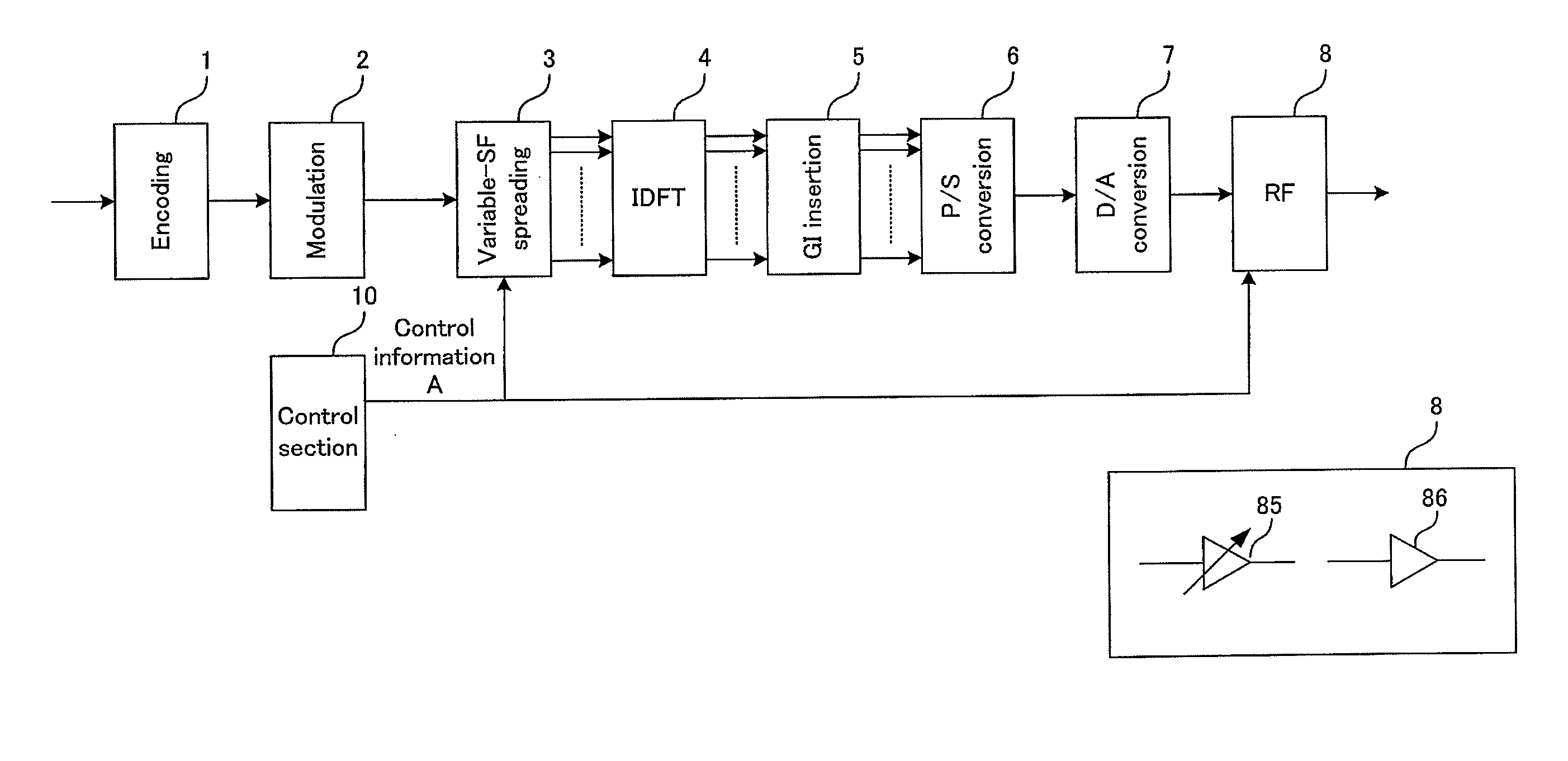
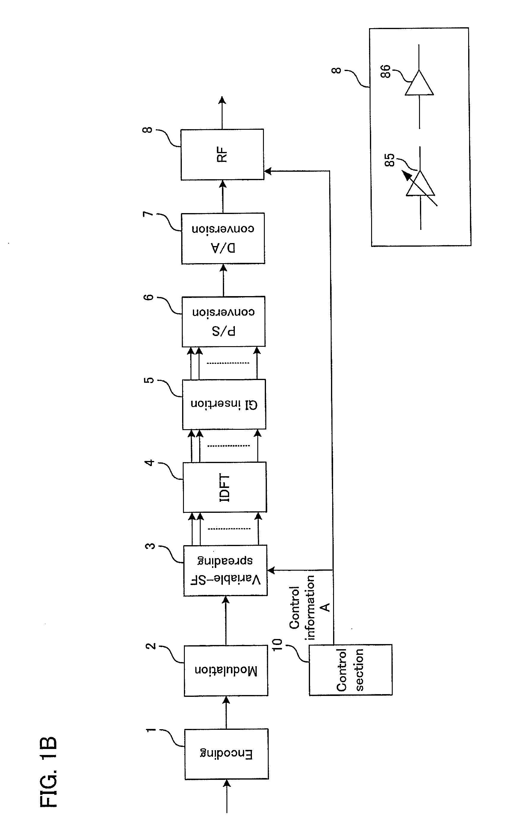
[0085]FIG. 8 is a functional block diagram showing an exemplary configuration of a transmission apparatus according to the invention. In the figure, blocks having the same functions as those shown in FIG. 1 are given the same reference numerals. The transmission apparatus shown in FIG. 8 further includes a repetition section 11 and a scrambling section 12 in addition to the configuration of FIG. 1B. From the control section 10, control information B is input to the repetition section 11. The repetition section 11 has the capability of repeating an input signal a number of times specified in control signal B. The scrambling section 12 has the capability of scrambling input data with a random code. The scrambling capability can be realized by multiplying an input signal by ±1 randomly in a simplest case. A random signal for scrambling can be of any of various patterns, but is preferably one that has no correlation with neighboring base stations. Also, to avoid stationary errors, it is...

third embodiment

[0116]As a specific example, downlink communication between the base station and terminal station B in which terminal A relays data will be described given the OFDMA system shown in the FIG. 18 shows an example of a frame format for use when relay is performed, where slots F1 to F3 at T3 (the cross-hatched slots) are slots allocated to communication from the base station to terminal A and slots T7 to T9 at F1 (the gray slots) are slots allocated to communication from terminal A to terminal B. It is assumed here that the base station does not perform transmission in slots T7 to T9 at F1.

[0117]From the base station to terminal A, data destined for terminal B is transmitted. For this transmission, there is no particular SF that is optimal, and any scheme may be used as long as terminal A can receive the data. However, to complete retransmission within the same frame, transmission of the data preferably finishes at an early stage in the frame (i.e., a stage with a smaller time sub-chan...


PUM


Abstract

A transmission apparatus according to the present invention includes: an encoding section; a modulation section; a variable-SF spreading section that performs spreading with variable SF according to control information A from a control section; an IDFT section that performs IDFT on output from the spreading section; a GI inserting section; a parallel / serial conversion section that converts output from the GI inserting section into a serial data sequence; a digital / analog conversion section; and an RF section that transmits a signal from an antenna after converting the signal to a frequency band for analog signal transmission and controlling it to an appropriate transmission power. The control section is configured to generate control information A for determining the variable SF and input the information A to the variable-SF spreading section and the RF section. In control information A, SF is varied depending on transmission power required.

Description

[0001]This application is a Divisional of co-pending application Ser. No. 12 / 677,742, filed on Mar. 11, 2010, the entire contents of which are hereby incorporated by reference and for which priority is claimed under 35 U.S.C. §120.TECHNICAL FIELD[0002]The present invention relates to a radio communication method and a radio transmission apparatus, and more particularly, to a radio communication method, a radio communication system, and a radio transmission apparatus for use in Orthogonal Frequency Division Multiplexing (OFDM) and Code Division Multiplexing (CDM) communication in which data communication is performed with a combination of multi-carrier signals typified by CDM-OFDM which transmits spread data using orthogonal codes.BACKGROUND ART[0003]In recent years, next-generation mobile communication systems have been actively studied and a one-frequency repeating cellular system in which individual cells use the same frequency band has been proposed as a scheme for improving effi...

Claims


Application Information

Patent Timeline
Patent Type & Authority Applications(United States)
IPC IPC(8): H04J11/00H04J13/00H04W72/04H04B1/69H04B1/707H04J13/20
CPCH04B1/692H04B1/707H04B2201/70706H04J13/0044H04J13/20H04W72/0446H04L5/026H04L27/2615H04L27/2626H04L27/2647H04B7/15H04L5/0021H04L27/2636
Inventor HAMAGUCHI, YASUHIROKUBOTA, MINORUNAMBA, HIDEOTOH, SHIMPEIYOKOMAKURA, KAZUNARI
Owner SHARP KK
Why Eureka
Try Eureka