Energy Saving System and Method for Devices with Rotating or Reciprocating Masses

a technology of energy saving system and energy saving method, which is applied in the direction of positive displacement liquid engine, machine/engine, motor direction control, etc., can solve the problems of inefficient generator, significant over-exceeding of generated energy, and mechanical solutions that have not worked, so as to achieve further energy saving, not consuming energy, and consuming energy

Active Publication Date: 2012-08-23
THE POWERWISE GRP
View PDF4 Cites 17 Cited by
  • Summary
  • Abstract
  • Description
  • Claims
  • Application Information

AI Technical Summary

Benefits of technology

[0025]According to one aspect of one or more embodiments of the present invention, a closed loop motor controller system reduces the supply voltage to a pump jack electric motor when the motor would be generating energy in open loop mode, when the phase angle between the voltage and current would be greater than 90 degrees. By reducing the supply voltage to the motor, the observed phase angle between voltage and current may be reduced to a value below 90 degrees. Under these conditions, the motor is still not consuming energy. Through pulse width modulation (“PWM”) techniques, the real power component may be reduced virtually to zero, leaving a reactive component greater than zero. By allowing some current flow, primarily of a reactive nature, an observable fee

Problems solved by technology

A pump jack system is such an inefficient generator that the quantity of consumed energy required to produce any generation significantly exceeds the generated energy.
However, the parameters of the downhole pumps and wells vary over time, so these mechanical solutions have not worked.
The changing volumes, densities, viscosities, weights, and other properties of materials and/or fluids pumped, such as gas, oil, water, and slurry, may greatly alter the combined weight of the rod string and the column of fluid, thereby affecting the balance of the system and the demand on the electric motor.
The influx of different fluids into the well over time will significantly impact the operation of the motor.
However, the problem was knowing when to turn the electric motor back on.
The microprocessor solutions also failed since the parameters of the downhole pumps and wells vary over time.
Energy generated from e

Method used


Image

  • Energy Saving System and Method for Devices with Rotating or Reciprocating Masses
  • Energy Saving System and Method for Devices with Rotating or Reciprocating Masses
  • Energy Saving System and Method for Devices with Rotating or Reciprocating Masses

Examples


Embodiment Construction

[0071]Specific embodiments of the present invention will now be described in detail with reference to the accompanying figures. Like elements in the various figures are denoted by like reference numerals for consistency. Further, in the following detailed description of embodiments of the present invention, numerous specific details are set forth to provide a more thorough understanding of the present invention. In other instances, well-known features have not been described in detail to avoid obscuring the description of embodiments of the present invention.

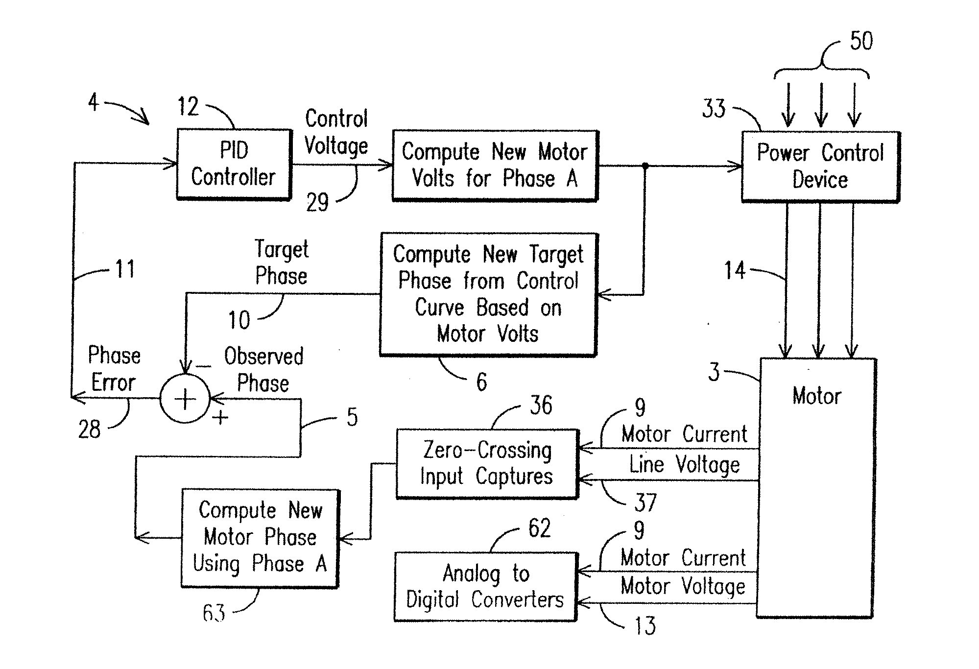
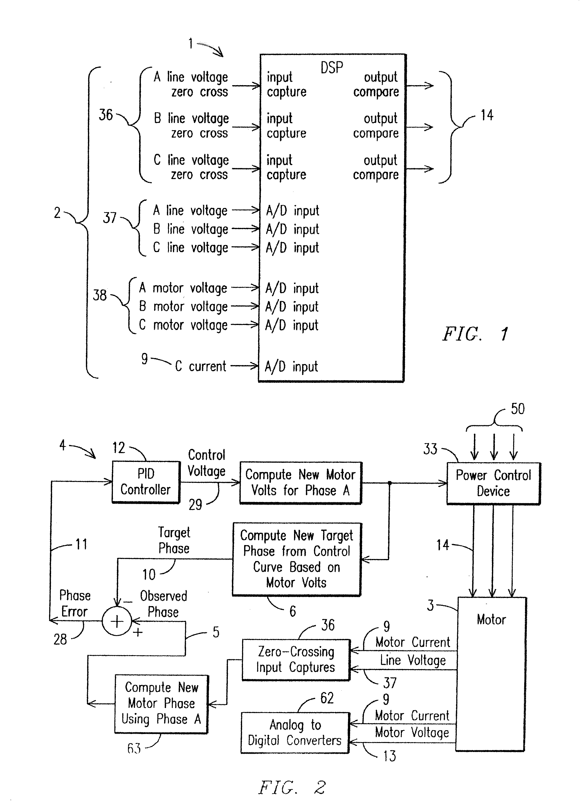
[0072]With reference to FIG. 1, a block diagram of a digital signal processor (“DSP”) 1 and hardware inputs and outputs is shown. The DSP 1 can observe the operational characteristics of a motor and make corrections to root mean square (“RMS”) voltage for the motor that is running and under closed loop control. Hardware inputs 2 capture phase zero crossing inputs 36, phase line voltage 37, phase motor voltage 38 and current 9 an...


PUM


Abstract

A system and method are provided for reducing the energy consumed by a pump jack electric motor by reducing the supply voltage to the motor when the motor would be generating energy in open loop mode. By substantially eliminating the energy generation mode, the braking action of the utility grid in limiting the acceleration of the motor and system that would otherwise occur is substantially removed. The motor and system will speed up, allowing the natural kinetic energy of the cyclic motion to perform part of the pumping action.

Description

CROSS-REFERENCE TO RELATED APPLICATIONS[0001]This application is a continuation-in-part of co-pending U.S. application Ser. No. 12 / 873,510 filed Sep. 1, 2010, which claims the benefit of U.S. Provisional Application No. 61 / 240,399 filed Sep. 8, 2009, and which co-pending application is a continuation-in-part of co-pending U.S. application Ser. No. 12 / 207,913 filed Sep. 10, 2008, which claims the benefit of both U.S. Provisional Application 61 / 135,402 filed Jul. 21, 2008 and U.S. Provisional Application 60 / 993,706 filed Sep. 14, 2007, all of which applications are hereby incorporated by reference for all purposes in their entirety.[0002]This application claims e benefit of U.S. Provisional Application No. 61 / 485,721 filed May 13, 2011, which application is hereby incorporated by reference for all purposes in its entirety.[0003]This application is a continuation-in-part of co-pending U.S. application Ser. No. 12 / 207,913 filed Sep. 10, 2008, which claims the benefit of both U.S. Provis...

Claims


Application Information

Patent Timeline
IPC IPC(8): F04B49/06
CPCH02P6/002F04B47/022H02P23/0072H02P6/182H02P6/28H02P23/24
Inventor LUMSDEN, JOHN L.KELLEY, PAUL H.VENKATARAMAN, VASAN
Owner THE POWERWISE GRP
Why Eureka
Try Eureka