
Network weapon system and method

a weapon system and network technology, applied in the field of network weapon systems and methods, can solve the problems of non-lethal weapons or lethal weapons

Inactive Publication Date: 2012-08-23
TELEROBOTICS
View PDF0 Cites 58 Cited by
  • Summary
  • Abstract
  • Description
  • Claims
  • Application Information

AI Technical Summary

Benefits of technology

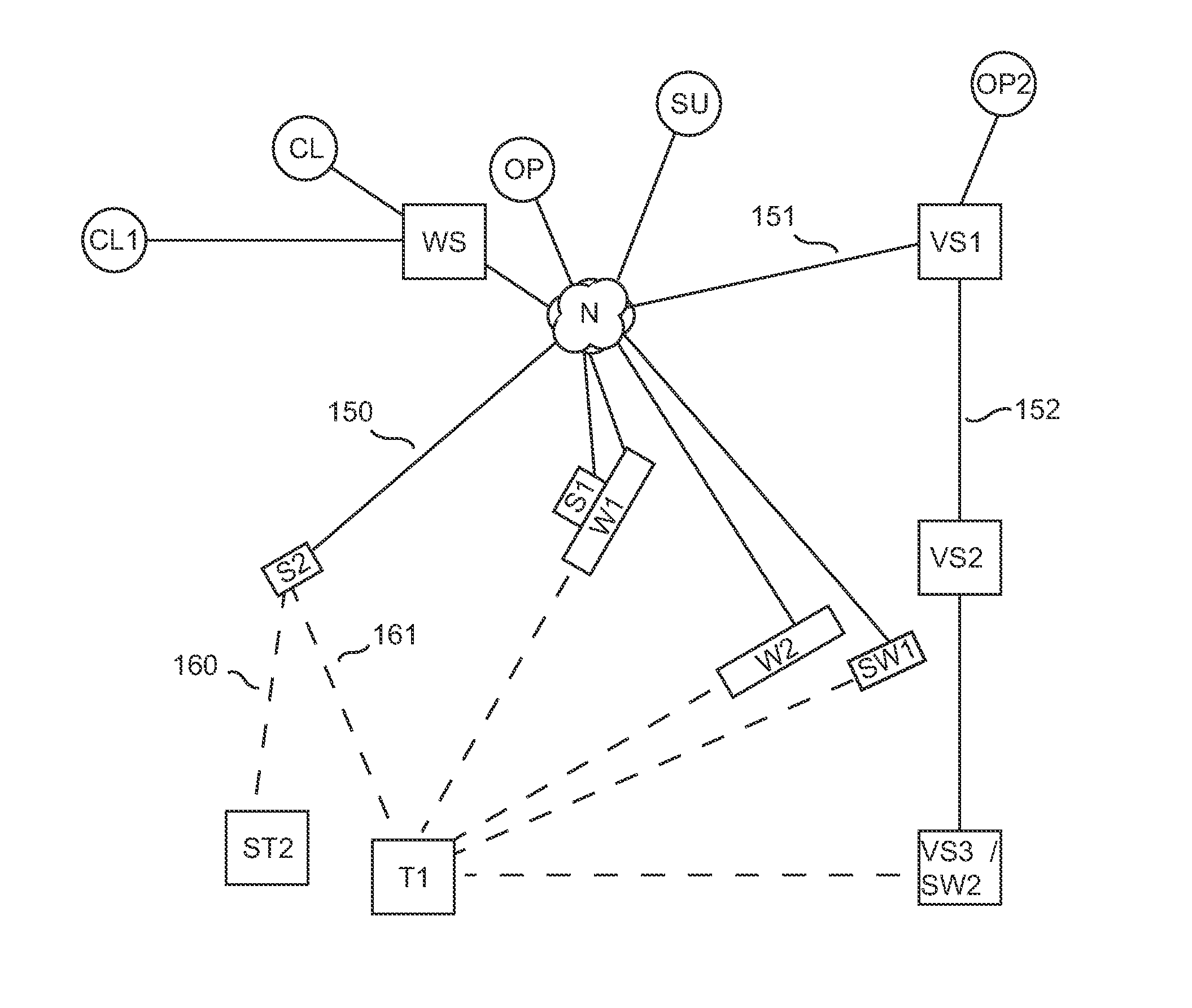
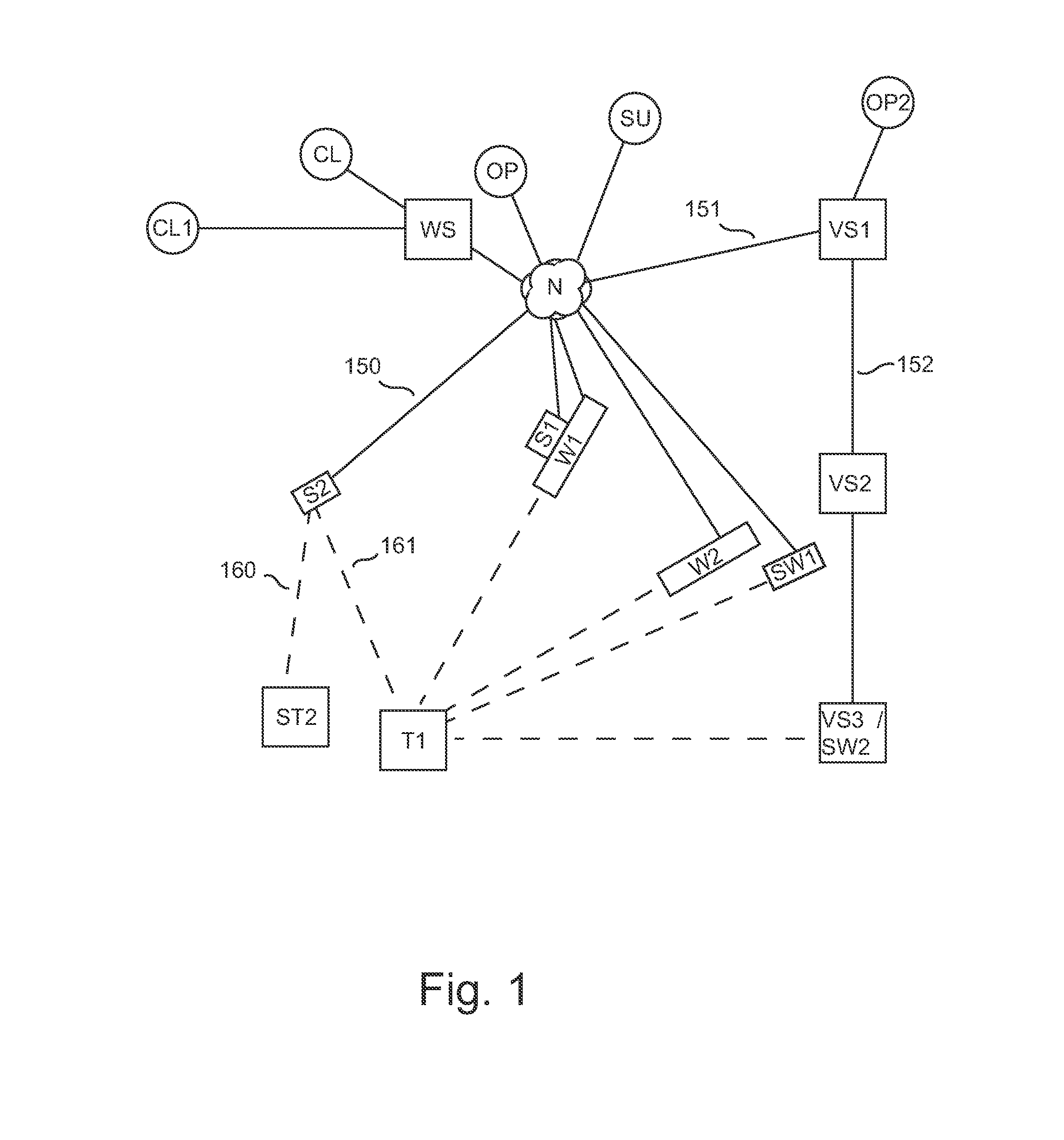
[0013]Embodiments of the invention analyze threats and assign at least one weapon to respond to the threat(s) sensed by the sensors. Analyzers are utilized to analyze the threats, assigners are utilized to assign weapons to threats and responders are utilized to operate the weapon system (whether real weapons, simulated weapons or portions of a video surveillance network are utilized). For example, more than one weapon (or simulated weapon) may be assigned to a given threat. When multiple threats appear to the system, the assignment and management of the particular weapons with respect to the particular threats is performed. Any algorithm may be utilized to assign or assist in the assignment of a weapon to a threat. For example, assigning the closest weapon to a threat or assigning an appropriate sized weapon to a threat (large gun to a vehicle threat versus a small caliber weapon to a human threat). In one or more embodiments of the invention, a user selection of a threat on a map for instance may be utilized to assign a weapon or a pick list of weapons that are capable of responding to the threat. This type of assistance greatly aides remotely operated weapons systems when there are multiple threats, multiple weapons / sensors and multiple operators.
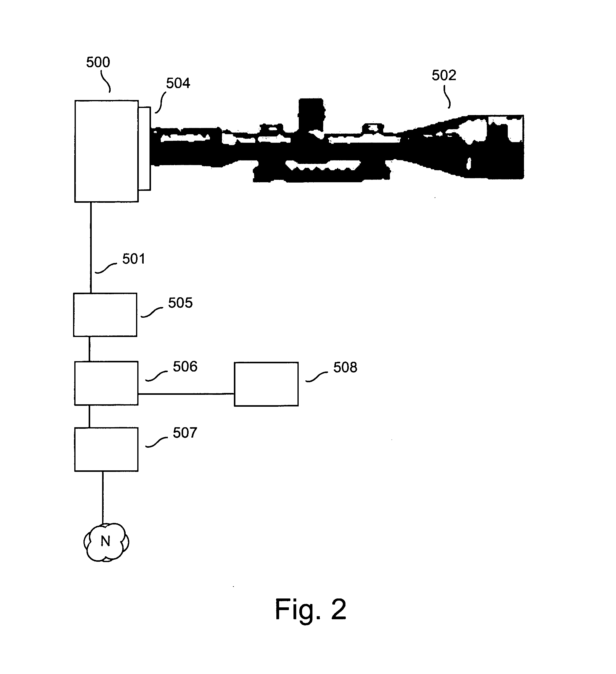
[0014]Embodiments of the invention may also be configured to enable an operator to interact with at least one sensor configured to operate as a simulated weapon over a network. Sensors may be collocated or distantly located from actual weapons and there may be a different number of weapons, simulated weapons and sensors in a configuration. Sensors, weapons and simulated weapons may be dynamically added or removed from the system without disrupting the operation of the system. Sensors that simulate weapons are transparently interchangeable with actual weapons. Replacing sensors that simulate weapons with actual weapons allows for existing systems to upgrade and add more weapons without requiring modifications to the system, for example no additional wiring. Simulated actors and events may be injected into the system with results generated from operator gestures simulated and recorded for later analysis. For example, virtual soldiers that move or fire may be injected into the displays of operators. Injecting actors allows for simulated training without requiring live firing of weapons. An operator may control more than one weapon and / or simulated weapon at a time and may obtain sensor data output from more than one sensor at a time. Embodiments of the invention allow for the assignment of weapons or simulated weapons to threats whether simulated or real threats.
[0015]Embodiments of the invention may also be configured to enable an operator to interact with a video surveillance system including at least one sensor. The sensor may be configured to operate as a simulated weapon, or may be replaced by or augmented with a real weapon and in either case the simulated or real weapon is controlled over a network. The network may include the local video surveillance network or a network linking with a remotely operated weapon system. The integration of an existing video surveillance system with a network of remotely operated weapons and / or weapon simulators enables use of the resources of either system by the other system and enables a passive video surveillance system to become an active projector of lethal or non-lethal force. Pan and tilt cameras that exist in a legacy video surveillance system or newly added pan and tilt cameras may be utilized for real or simulated weapons, and cameras that do not pan and tilt may simulate pan and tilt functions through image processing. In addition, a video surveillance sensor may be automatically panned to follow an object targeted by the remotely operated weapon system or the remotely operated weapons may track an object that is being followed by at least one of the video surveillance sensors. Intelligent switching between sensors is accomplished when a sensor in the video surveillance system or remotely operated weapon system can no longer track an object thereby allowing any other available sensor to track an object. An operator may control more than one weapon and / or simulated weapon or video surveillance camera (that may act as a simulated weapon for example) at a time and may obtain sensor data output from more than one sensor at a time.

Problems solved by technology

Weapons may be lethal or non-lethal.

Method used


Image

  • Network weapon system and method
  • Network weapon system and method
  • Network weapon system and method

Examples


Embodiment Construction

[0043]A network weapon system and method will now be described. In the following exemplary description numerous specific details are set forth in order to provide a more thorough understanding of embodiments of the invention. It will be apparent, however, to an artisan of ordinary skill that the present invention may be practiced without incorporating all aspects of the specific details described herein. In other instances, specific features, quantities, or measurements well known to those of ordinary skill in the art have not been described in detail so as not to obscure the invention. Readers should note that although examples of the invention are set forth herein, the claims, and the full scope of any equivalents, are what define the metes and bounds of the invention.

[0044]Embodiments of the invention enable the operation of at least one weapon selected from a set of disparate weapons over a computer network such as a private network or LAN or public network such as the Internet....


PUM


Abstract

Allows for the assignment of threat(s) to weapon(s) to allow operators to coordinate actions. Enables dynamic discovery and operation weapon(s), sensor(s) over a local or public network so available weapons can be selected by operators. Sensors may act as simulated weapons and may also reside in a video surveillance system (VSS). Sensors may be collocated or away from weapons which may differ in number. Sensors simulating weapons are transparently interchangeable with actual weapons. Simulated actors and events may be injected into system with operator gestures recorded for later analysis. Operator may control more than one weapon or sensor at a time. Operator user interface may be cloned onto another computer for real-time supervision or for later use. Integration of existing VSS with a network of remotely operated weapons or simulated weapons enables a passive video surveillance system upgrade to become a projector of lethal or non-lethal force.

Description

[0001]This application is a continuation in part of U.S. patent application Ser. No. 10 / 907,825 filed Apr. 17, 2005 which is a continuation in part of U.S. patent application Ser. No. 10 / 907,143 filed Mar. 22, 2005 which is a continuation in part of U.S. Pat. No. 7,159,500 filed Oct. 12, 2004 the specifications of which are all hereby incorporated herein by reference.BACKGROUND OF THE INVENTION[0002]1. Field of the Invention[0003]Embodiments of the invention described herein pertain to the field of weapon systems and methods. More particularly, but not by way of limitation, these embodiments enable an operator to interact with at least one weapon and / or at least one sensor over a network such as a LAN or the Internet wherein one or more sensors may be configured to simulate a weapon and wherein weapons and simulated weapons may be integrated with a video surveillance system.[0004]2. Description of the Related Art[0005]A network allows multiple computers or other hardware components ...

Claims


Application Information

Patent Timeline
Patent Type & Authority Applications(United States)
IPC IPC(8): F41G3/26
CPCF41A17/063F41A33/00F41G9/00F41G3/04F41G3/14F41G3/02
Inventor GOREE, JOHNFELDMAN, BRIAN
Owner TELEROBOTICS
Learn More