
Regenerative cell extraction unit and regenerative cell extraction system

a regenerative cell and extraction unit technology, applied in the field of regenerative cell extraction unit and system, can solve the problems of inefficient fat tissue extraction, insufficient automation, fat tissue exposed to contamination risk, etc., and achieve the effect of increasing efficiency

Active Publication Date: 2012-08-23
PUREBIO & TECH +2
View PDF2 Cites 36 Cited by
  • Summary
  • Abstract
  • Description
  • Claims
  • Application Information

AI Technical Summary

Benefits of technology

"The present invention relates to a regenerative cell extraction unit and system that can automatically perform all processes from collecting fat tissue to extracting stem cells with increased efficiency. The unit includes a main container, a hollow first discharge pipe, a suction device, and a plurality of protruding housing portions. The system includes a regenerative cell separation unit and the regenerative cell extraction unit. The main technical effects of the invention include increased efficiency in extracting stem cells from fat tissue, improved separation of stem cells from other components, and simplified operation."

Problems solved by technology

While many devices have been developed to collect cells from fat tissue, they are not efficient in extracting fat tissue or are not fully automated—that is, of all processes from collecting fat tissue to processing the fat tissue, some processes should be performed manually.
In addition, since these devices are not sealed completely, fat tissue is exposed to a risk of contamination while being collected and processed.

Method used


Image

  • Regenerative cell extraction unit and regenerative cell extraction system
  • Regenerative cell extraction unit and regenerative cell extraction system
  • Regenerative cell extraction unit and regenerative cell extraction system

Examples


Embodiment Construction

[0031]Hereinafter, a regenerative cell extraction system and unit according to an exemplary embodiment of the present invention will be described in greater detail with reference to the accompanying drawings.

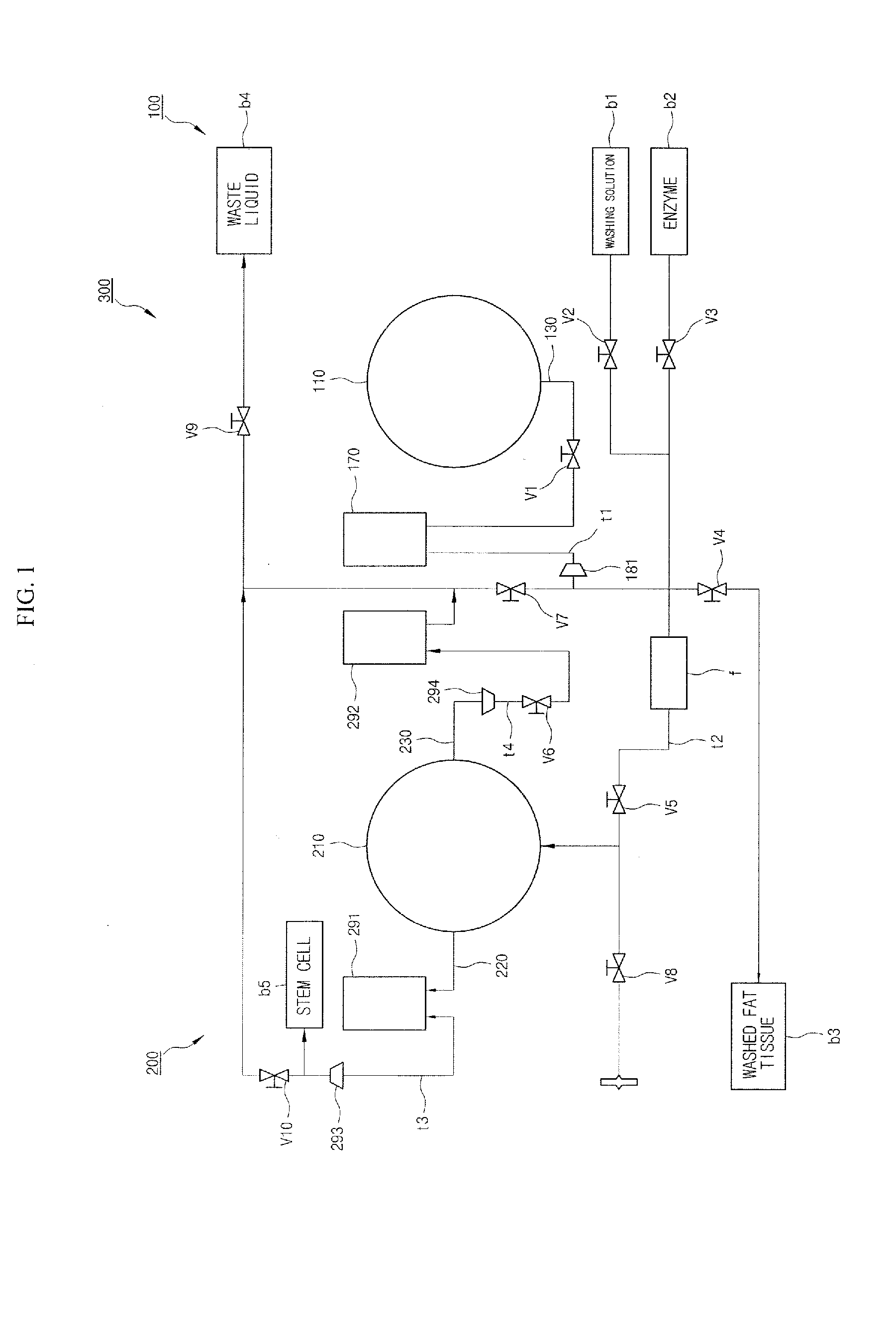
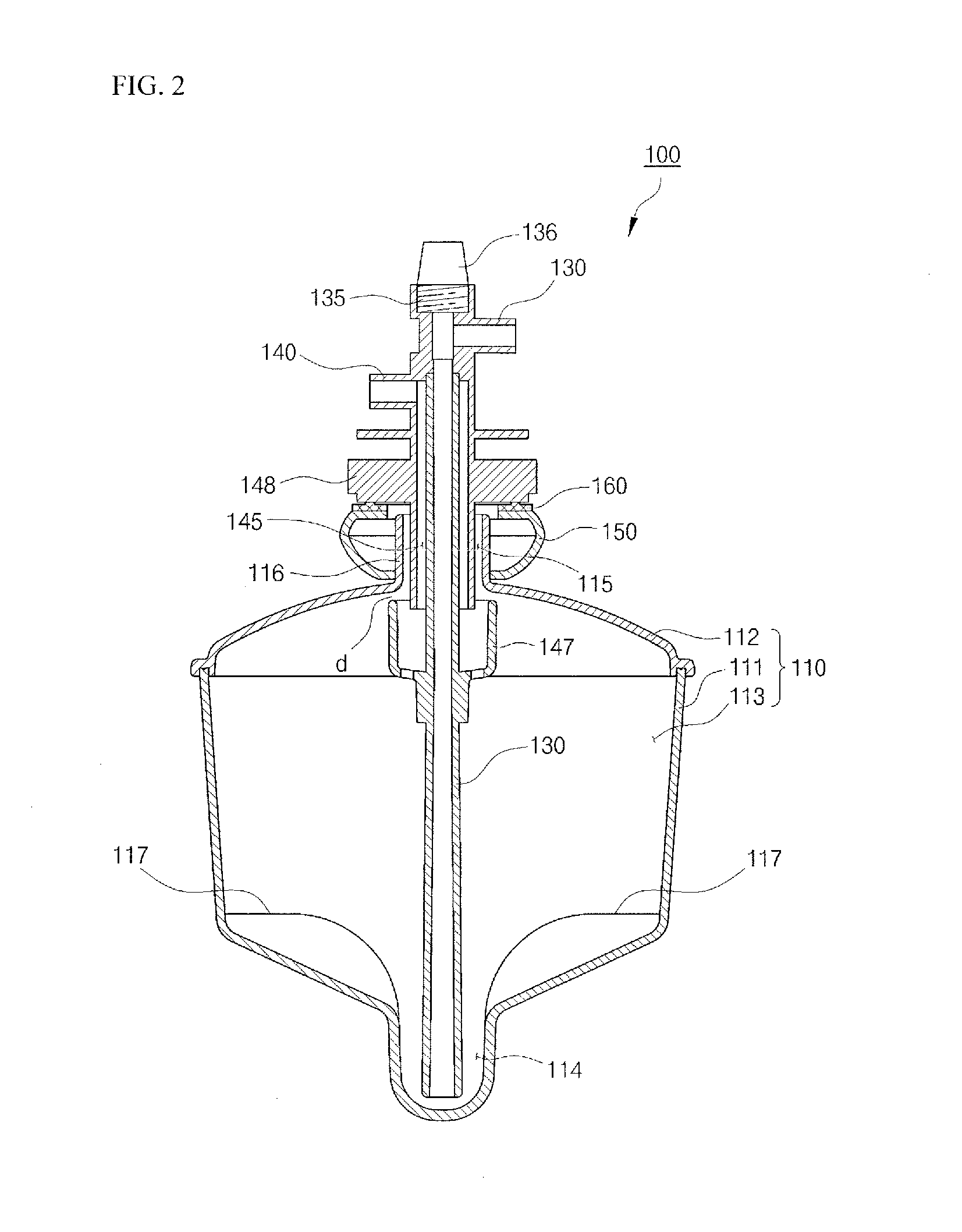
[0032]FIG. 1 is a schematic diagram illustrating the configuration of a regenerative cell extraction system 300 according to an exemplary embodiment of the present invention. FIG. 2 is a schematic cross-sectional view of a regenerative cell separation unit 100 shown in FIG. 1.

[0033]Referring to FIGS. 1 and 2, the regenerative cell extraction system 300 according to the current exemplary embodiment includes the regenerative cell separation unit 100 and a regenerative cell extraction unit 200. The regenerative cell separation unit 100 and the regenerative cell extraction unit 200 are connected to each other by pumps and tubes. In addition, the regenerative cell separation unit 100 and the regenerative cell extraction unit 200 are fitted to a rotating jig(not shown). Thus, while be...


PUM


Abstract

Provided is a regenerative cell extraction system. The regenerative cell extraction system includes: a regenerative cell separation unit which separates fat tissue; and a regenerative cell extraction unit. The regenerative cell separation unit includes: a sub container which is rotated by a torque applied from an external source and includes a space in which fat tissue is housed; a hollow main pipe which is inserted into the sub container; and a pump which is connected to the main pipe. In addition, the regenerative cell extraction unit receives a regenerative cell-containing substance, which is obtained after the fat tissue is centrifuged by the regenerative cell separation unit, from the regenerative cell separation unit, and extracts regenerative cells from the substance by centrifuging the substance. The regenerative cell extraction unit includes: a main container which is rotated by a torque applied from an external source; a hollow first discharge pipe which is inserted into the main container; and a suction device which is connected to the first discharge pipe; and a plurality of protruding housing portions which bulge outwards along a radius direction with respect to a center of rotation of the main container to accommodate relatively heavy components among components separated from the substance.

Description

CROSS-REFERENCE TO RELATED APPLICATION[0001]This application claims the benefit under 35 U.S.C. §119(a) of a Korean Patent Application No. 10-2009-0102085, filed on Oct. 27, 2009, the entire disclosure of which is incorporated herein by reference for all purposes.BACKGROUND[0002]1. Field[0003]The following description relates to a regenerative cell extraction unit and system, and more particularly, to a system for extracting regenerative cells such as fat-derived stem cells by centrifuging fat tissue and an extraction unit used in the system.[0004]2. Description of the Related Art[0005]Stem cells are defined as cells that have clonogenic and self-renewing capabilities and that differentiate into multiple cell lineages. Whereas embryonic stem cells are derived from mammalian embryos in the blastocyst stage and have the ability to generate any terminally differentiated cell in the body, adult stem cells are part of tissue-specific cells of the postnatal organism into which they are co...

Claims


Application Information

Patent Timeline
Patent Type & Authority Applications(United States)
IPC IPC(8): B04B7/00
CPCC12M47/04C12M45/05B04B11/02B04B5/0442C12M33/10C12M1/10C12M1/12C12Q1/24C12N5/0662
Inventor DO, BYUNG-ROKLEE, JUNG-KYUKIM, JI-HYANGKANG, SUNG-GUUPAK, SEUNG-HOONKIM, MYUNG-JINSHIN, KYU-CHULKIM, CHUL-GEUNYOON, YUNG-DAL
Owner PUREBIO & TECH
Learn More