
Six Degree Spine Stabilization Devices and Methods

a spine and stabilization device technology, applied in the direction of prosthesis, spinal implants, coatings, etc., can solve the problems of spinal disc displacement or damage, leg pain, loss of muscle control, or even paralysis, and achieve the effect of directional stability

Active Publication Date: 2012-08-23
GLOBUS MEDICAL INC
View PDF11 Cites 17 Cited by
  • Summary
  • Abstract
  • Description
  • Claims
  • Application Information

AI Technical Summary

Benefits of technology

[0008]The implant of the invention is operative, when positioned between adjacent bones of a joint, such as adjacent vertebrae, to stabilize the joint. The implant further enables a natural kinematic movement of the joint, while limiting movement beyond a therapeutic range of motion.
[0009]A flexible core is provided with an inflection region of greater flexibility, which enables a displacement or changed orientation of opposed engaging surfaces of the core. In one embodiment, the core tapers at one end to form the inflection region, and which may deform or buckle to enable a relative angular displacement of engaging surfaces.
[0011]A tether, or lanyard may be provided, operative to limit a maximum displacement of the core and one or both of the first and second support components. The lanyard is affixed to two of either core and one or both support components. The lanyard is formed of a flexible material which does not prevent movement within an intended range of motion of the implant, and may advantageously be formed of a resilient material, to avoid an abrupt relative cessation of movement at a limit of travel.
[0028]Similarly, both sides of the core may be curved, each side mateable with a curved surface of a support component, for example, forming two convex surfaces. Mating surfaces on both sides of the core, for example, operate to foster a desired kinematic movement, and maintain a desired ligament tension throughout the expected range of motion. It should be understood, however, that in accordance with the invention, either surface may be either convex, concave, or flat, as the therapeutic needs of the patient dictate. In use, a configuration with a curved mating surface enables all six degrees of movement as described above, however, due to the mating curved slidable engaging surfaces, additional directional stability is provided.
[0029]In a further embodiment, the core is provided with a flat surface at a second engaging surface, which is matably connectable to a flat core engaging surface of a support component. One or more pins pass through pin bores or apertures provided in the core and support component, locking the two components together. In addition, a snap fit engagement between recessed and projecting portions of the core and a support component may be provided to further secure the core and support component together.
[0034]All elements of implant may be made from a flexible material, although the core, in particular, flexes in order to accommodate an angular displacement of first and second support components. As the joint is flexed or extended, the flexible and or resilient material of the core may bulge or stretch to enable an angular displacement of opposing engaging surfaces. Additionally, or alternatively, an inflection region provides a relatively weaker region of the core, which is adapted through thickness and or shape to facilitate bending of the core.

Problems solved by technology

The spinal disc may be displaced or damaged due to trauma, disease, degenerative defects, or wear over an extended period.
The mass of a herniated or “slipped” nucleus tissue can compress a spinal nerve, resulting in leg pain, loss of muscle control, or even paralysis.
As these overlapping laminated plies of the annulus begin to buckle and separate, either circumferential or radial annular tears may occur, which may contribute to persistent or disabling back pain.
Adjacent, ancillary spinal facet joints will also be forced into an overriding position, which may create additional back pain.
Whenever the nucleus tissue is herniated or removed by surgery, the disc space will narrow and may lose much of its normal stability.
While this treatment alleviates the pain, all discal motion is lost in the fused segment.
Ultimately, this procedure places a greater stress on the discs adjacent to the fused segment as they compensate for lack of motion, perhaps leading to premature degeneration of those adjacent disc.
Many of the current designs for prosthetic discs are large and inflexible.
In addition, prosthetic disc sizes and other parameters limit the approach a surgeon may take to implant the devices.

Method used


Image

  • Six Degree Spine Stabilization Devices and Methods
  • Six Degree Spine Stabilization Devices and Methods
  • Six Degree Spine Stabilization Devices and Methods

Examples


Embodiment Construction

[0047]In the description which follows, any reference to direction or orientation is intended primarily and solely for purposes of illustration and is not intended in any way as a limitation to the scope of the present invention. Also, the particular embodiments described herein are not to be considered as limiting of the present invention.

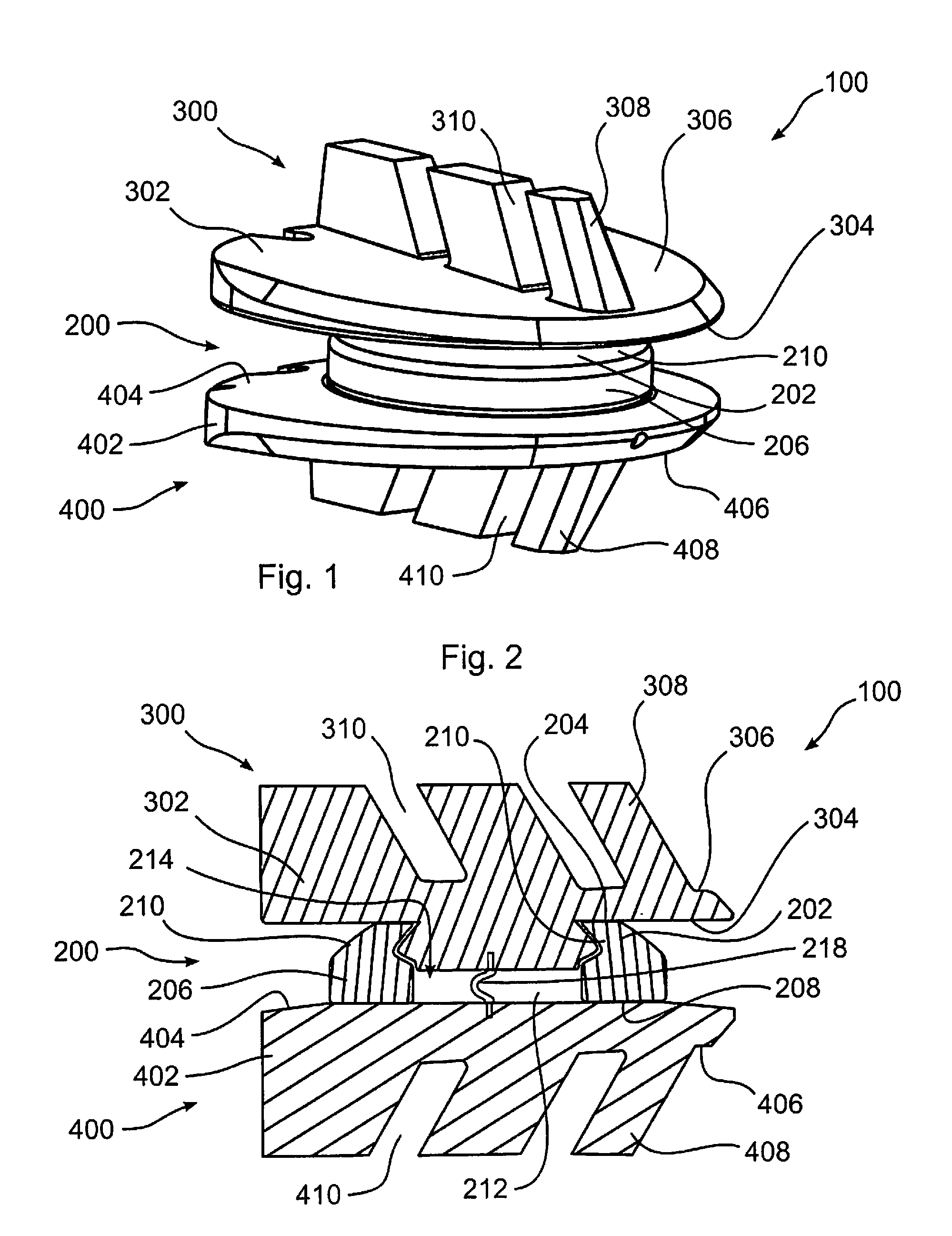
[0048]Referring now to the figures, in which like reference numerals refer to like elements, FIGS. 1 and 2 illustrate an implant 100 in accordance with the invention, including a flexible core 200, a first support component 300, operative to contact a first engaging surface 204 of core 200, and a second support component 400, operative to contact an opposing second engaging surface 208 of core 200.

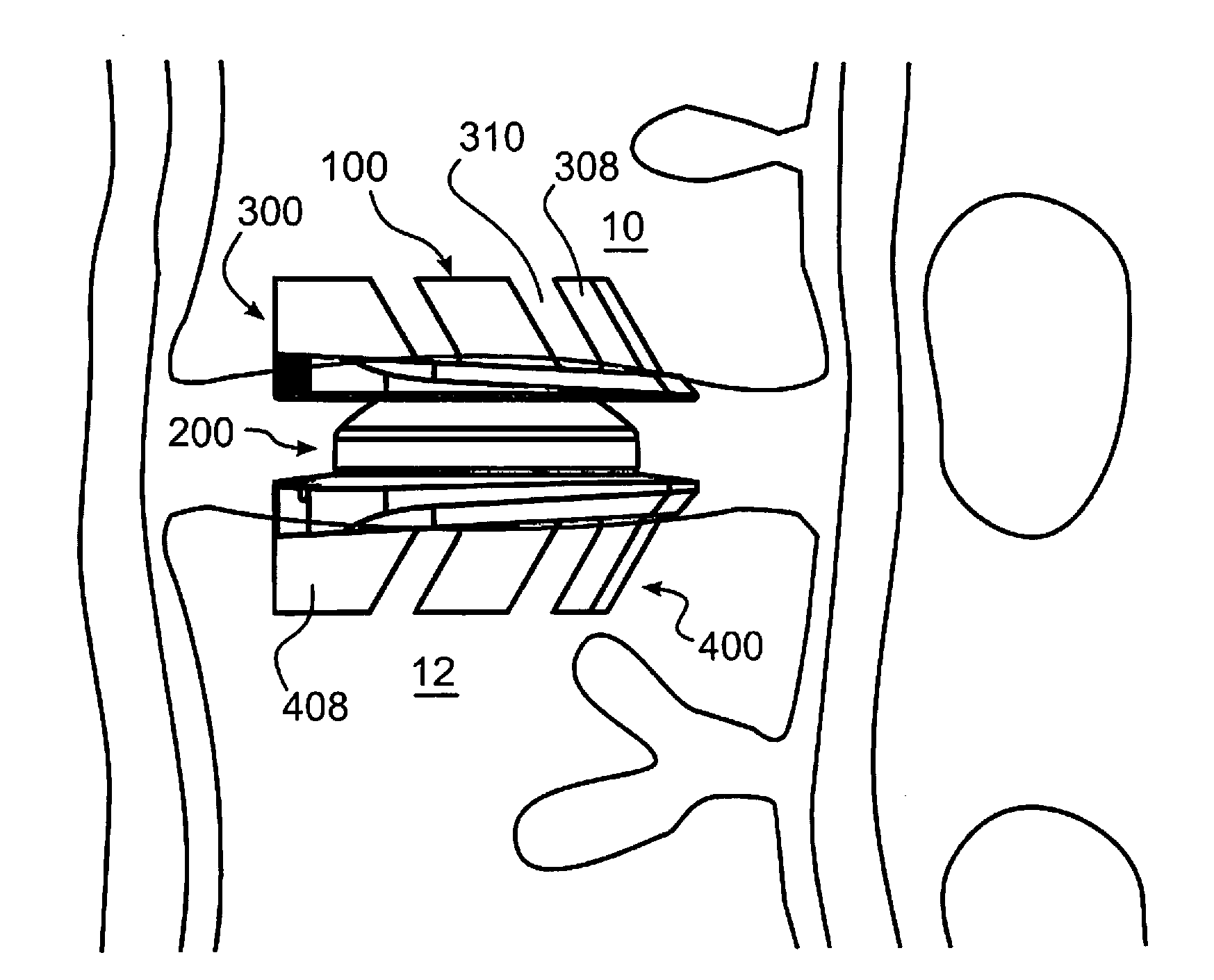
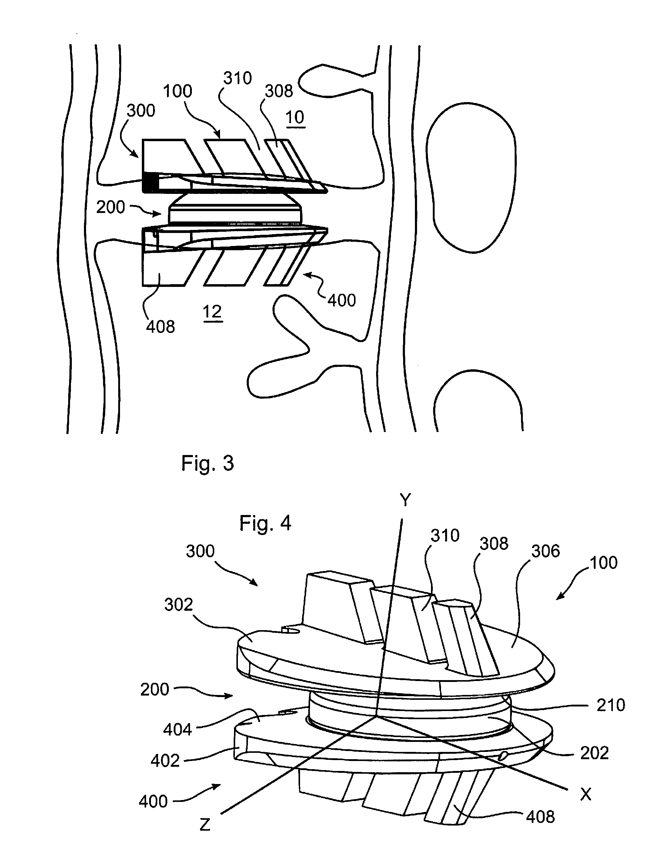
[0049]With reference to FIG. 3, implant 100 is operative, when positioned between adjacent bones of a joint, such as for example vertebrae 10, 12, to stabilize a joint formed by adjacent vertebrae. Implant 100 further enables natural kinematic movement o...


PUM

PropertyMeasurementUnit
sizeaaaaaaaaaa
pressureaaaaaaaaaa
relative distanceaaaaaaaaaa

Abstract

An implant stabilizes two adjacent bones of a joint, while enabling a natural kinematic relative movement of the bones. Support components are connected to each bone of the joint, and a flexible core is interposed between them. The core and at least one of the support components are provided with a smooth sliding surface upon which the core and support component may slide relative to each other, enabling a corresponding movement of the bones. The surfaces may have a mating curvature, to mimic a natural movement of the joint. The core is resilient, and may bend or compress, enabling the bones to move towards each other, and or to bend relative to each other.

Description

FIELD OF THE INVENTION[0001]This invention relates to stabilizing adjacent vertebrae of the spine, after surgery or trauma, while preserving a natural kinematic signature.BACKGROUND OF THE INVENTION[0002]Intervertebral devices are used to address diseases or disorders of the spine, or to address damage due to trauma. These devices operate, for example, to stabilize, guide, or limit movement of adjacent vertebrae, while bearing weight.[0003]The spinal disc may be displaced or damaged due to trauma, disease, degenerative defects, or wear over an extended period. A disc herniation occurs when the annulus fibers are weakened or torn and the inner tissue of the nucleus becomes permanently bulged, distended, or extruded out of its normal, internal annulus confines. The mass of a herniated or “slipped” nucleus tissue can compress a spinal nerve, resulting in leg pain, loss of muscle control, or even paralysis. Alternatively, with discal degeneration, the nucleus loses its water binding abi...

Claims


Application Information

Patent Timeline
Patent Type & Authority Applications(United States)
IPC IPC(8): A61F2/44
CPCA61F2/4425A61F2310/00976A61F2002/30013A61F2002/30014A61F2002/30069A61F2002/30385A61F2002/30392A61F2002/30393A61F2002/30398A61F2002/30433A61F2002/30448A61F2002/30462A61F2002/30472A61F2002/30607A61F2002/30616A61F2002/30649A61F2002/30652A61F2002/30658A61F2002/30673A61F2002/30772A61F2002/3081A61F2002/30878A61F2002/30892A61F2002/30906A61F2002/30927A61F2002/3098A61F2002/443A61F2310/00011A61F2310/00023A61F2310/00029A61F2310/00179A61F2310/00407A61F2310/0097A61F2/4611A61F2310/00059A61F2002/30011A61F2002/30925A61F2/3094A61F2/442
Inventor BENNETT, JEFFDWYER, EDWARD
Owner GLOBUS MEDICAL INC
Learn More