Control method for automatically raising operational speed of engine or motor for energy saving and extension of automobile lifespan

Inactive Publication Date: 2012-08-23
WANG SHIUAN SHENG
View PDF3 Cites 8 Cited by
  • Summary
  • Abstract
  • Description
  • Claims
  • Application Information

AI Technical Summary

Benefits of technology

[0004]The primary objective of the present invention is to provide a control method for automatically raising rotational speed, which helps controlling the temperature of an automatic transmission box not to fast and greatly increase and to reduce the potential risk of damage of parts of the transmission box, so as to extend the lifespan of the transmission box.
[0005]Another objective of the present invention is to provide a control method for automatically raising rotational speed, which helps protecting the engine or motor that supplies power to an automobile from being damaged by improper reaction of external force so as to improve the life span thereof.
[0006]A further objective of the present invention is to provide a control method for automatically raising rotational speed, which helps reducing fuel consumption of automobiles and thus saving energy.
[0007]To achieve the above objectives, the present invention provides a control method for automatically raising rotational speed, which

Problems solved by technology

This makes it impossible to have the engine or motor of the car operated in such a way to correspond to the various situations of roads or streets.
This causes a waste of kinetic energy and also causes unnecessary consumption of fuel and additional wear of moving parts.
This causes fast abrasion of surface teeth and may eventually fail functioning, leading to slipping.
Such damage may get severe when the rotational speed difference between the two is great.
This operation helps reducing unnecessary fuel consumption, but it may cause a problem for it needs, at the time when power is required,

Method used


Image

  • Control method for automatically raising operational speed of engine or motor for energy saving and extension of automobile lifespan
  • Control method for automatically raising operational speed of engine or motor for energy saving and extension of automobile lifespan

Examples


Example

[0011]The following descriptions are exemplary embodiments only, and are not intended to limit the scope, applicability or configuration of the invention in any way. Rather, the following description provides a convenient illustration for implementing exemplary embodiments of the invention. Various changes to the described embodiments may be made in the function and arrangement of the elements described without departing from the scope of the invention as set forth in the appended claims.

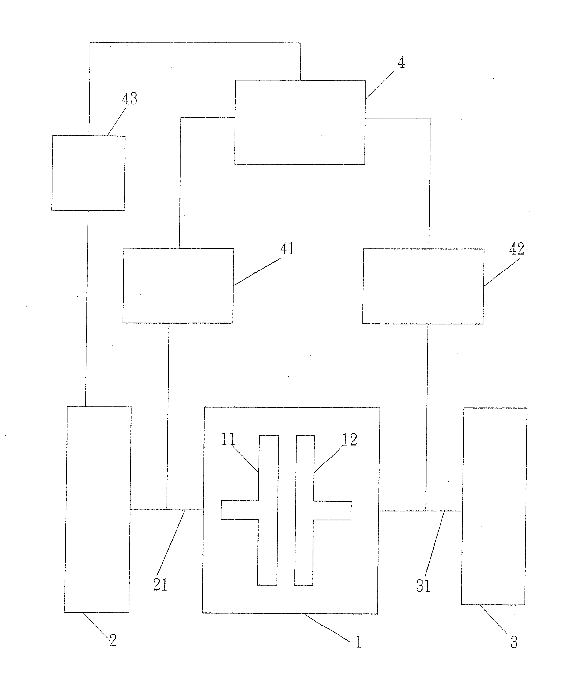
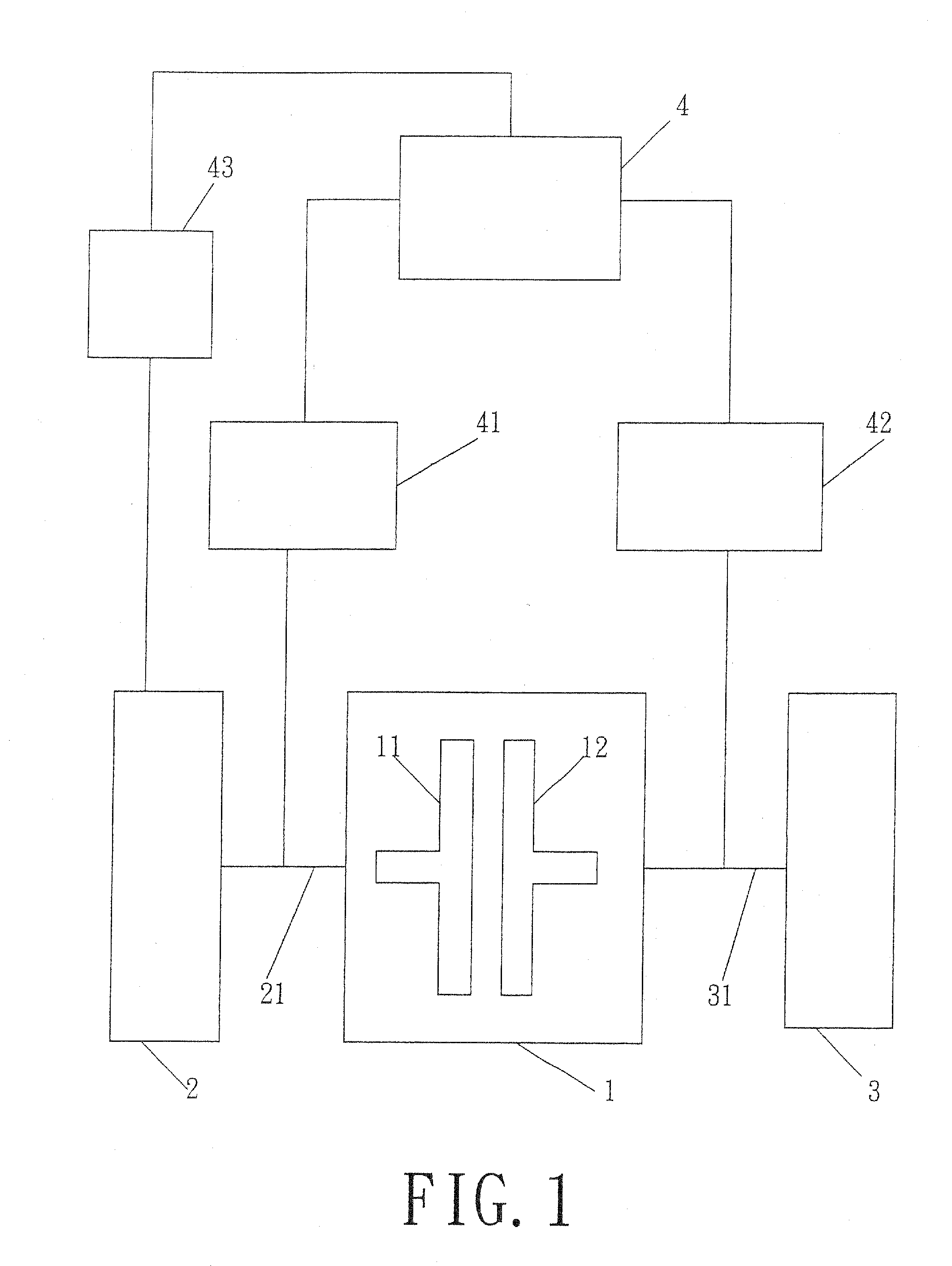
[0012]FIG. 1 is a schematic view illustrating a control method for automatically raising rotational speed of engine or motor for energy saving and extension of automobile lifespan according to the present invention, and a simplified schematic view showing transmission of power with a torque converter 1 is presented. The torque converter 1 comprises an impellor wheel 11 and a runner wheel 12 both contained in the torque converter 1. When the impellor wheel 11 and the runner wheel 12 engage each other...


PUM


Abstract

Provided is a control method for automatically raising rotational speed, in which two sensors are respectively mounted to power input side and power output side of a torque converter for detecting the rotational speeds of an impellor wheel and a runner wheel of the torque converter. The two sensors are connected to an on-automobile computer, which comprises a control device that raises the rotational speed of the engine or motor of the automobile, when a gearshift lever of the automobile is switched from a neutral position into a drive position under the condition that the automobile is in the neutral position and is moved by inertia thereof at a speed higher than 35 KM/H, order to cause an increase of the rotational speed of the impellor wheel to have the rotational speed of the impellor wheel slightly lower than the runner wheel with a rotational speed difference less than 300 rpm.

Description

TECHNICAL FIELD OF THE INVENTION[0001]The present invention generally relates to a control method for automatically raising operational speed of engine or motor for energy saving and extension of automobile lifespan, which controls the speed difference between the impellor wheel and the runner wheel of a torque converter so that when the gearshift lever of a car is switched from the neutral position into the drive position under the condition that the car is in the neutral position and is allowed to “inertia-drive” at a speed higher than 35 KM / H, the rotational speed of the engine or motor of the car is raised to have the impellor wheel of the torque converter increased to a level slightly lower than the rotational speed of the runner wheel with a rotational speed difference less than 300 rpm, whereby the fluid temperature of the automatic transmission box will not greatly increased and stable engagement can be achieved, and also, the lifespan of car transmission box is extended, ri...

Claims


Application Information

Patent Timeline
IPC IPC(8): B60W10/08B60W10/00B60W10/06
CPCB60W10/06B60W30/1882B60W2510/0241F02D41/023F02D31/001F02D41/0215
Inventor WANG, SHIUAN-SHENG
Owner WANG SHIUAN SHENG
Why Eureka
Try Eureka