

Physical quantity detector and method of manufacturing the same
- Summary
- Abstract
- Description
- Claims
- Application Information
AI Technical Summary
Benefits of technology
Problems solved by technology
Method used
Image

Examples
first embodiment
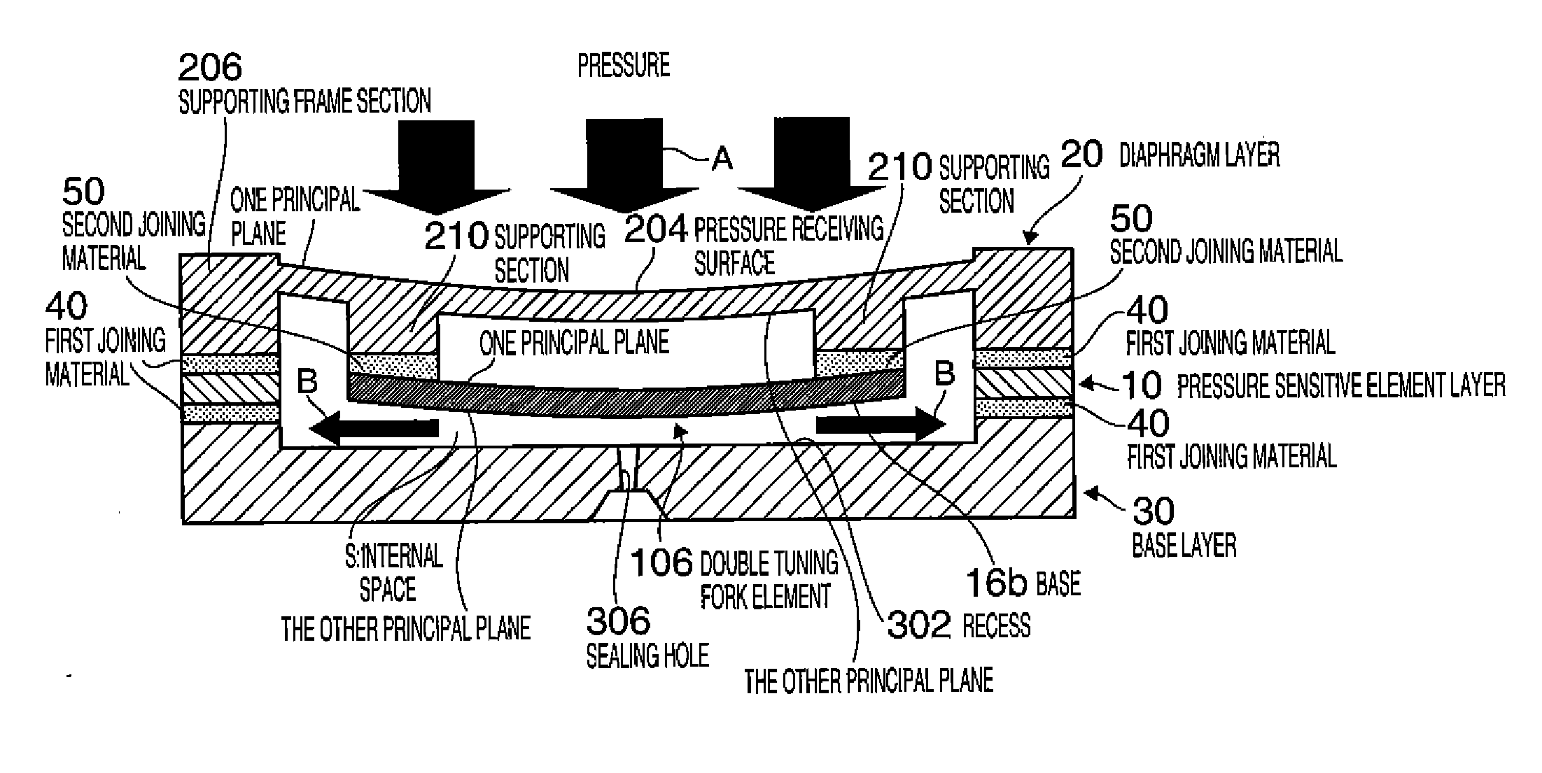
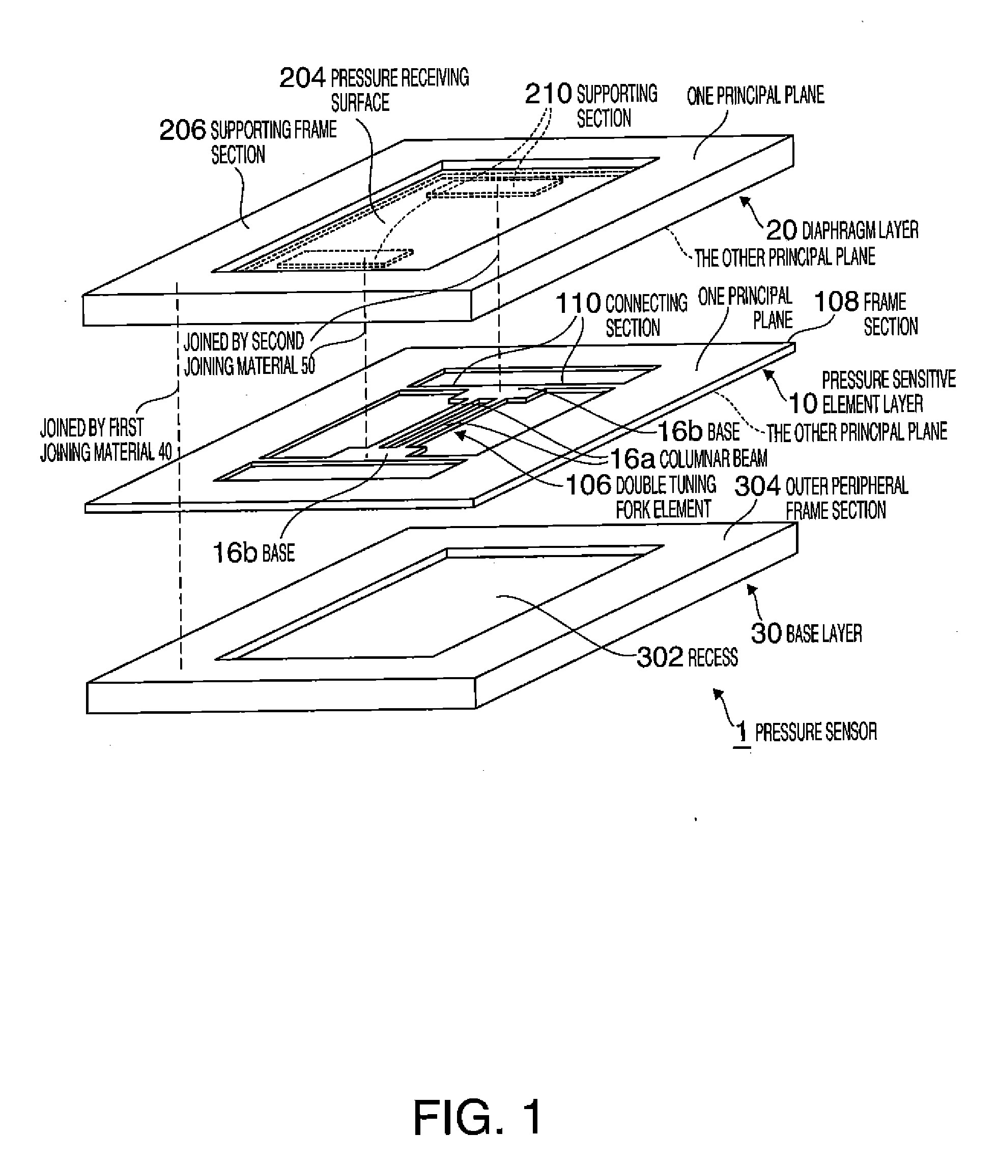
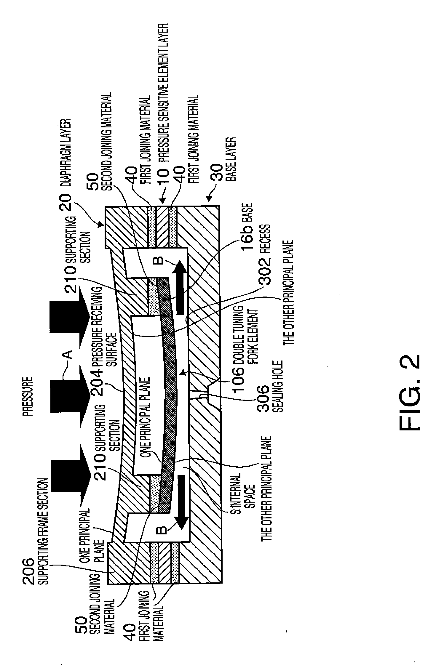
[0054]FIG. 1 is an exploded perspective view of a pressure sensor according to a FIG. 2 is a schematic sectional view for explaining the operation of the pressure sensor. In FIG. 1, joining materials are not shown.
[0055]As shown in FIG. 1, a pressure sensor 1 includes a pressure sensitive element layer 10 and a diaphragm layer (corresponding to “diaphragm”) 20 and a base layer (corresponding to “base”) 30 that respectively cover to hermetically seal one principal plane side and the other principal plane side of the pressure sensitive element layer 10. The layers 10, 20, and 30 include quartz crystal substrates as base materials.
[0056]The pressure sensitive element layer 10 includes, in the center thereof, a double tuning fork element 106 functioning as a pressure sensitive element and includes a frame section 108 having a frame shape that surrounds the double tuning fork element 106. In this embodiment, the frame section 108 corresponds to “fixing section”. The double tuning fork e...
second embodiment
[0100]In the second embodiment, the diaphragm layer 20, and the base layer 30 configure a container. The internal space S is formed by a space surrounded by the diaphragm layer 20 and the base layer 30.
[0101]As a method of manufacturing the pressure sensor 1A, a method same as the method in the first embodiment can be used. However, in a step in the second embodiment corresponding to step 5 shown in FIG. 5 in the first embodiment, in a state in which one principal plane of the diaphragm layer 20 is faced upward, when the supporting frame section 206 of the diaphragm layer 20 and the outer peripheral frame section 304 of the base layer 30 are set in contact with each other via the first joining material 40, since a frame section is absent around the double tuning fork element 106 in the second embodiment, the double tuning fork element 106 cannot be supported in the internal space S. Therefore, in the second embodiment, step 5 and subsequent steps only have to be performed, in a stat...
PUM
| Property | Measurement | Unit |
|---|---|---|
| Temperature | aaaaa | aaaaa |
| Pressure | aaaaa | aaaaa |
| Melting point | aaaaa | aaaaa |
Abstract
Description
Claims
Application Information