Dynamic vibration absorber

a vibration absorber and dynamic technology, applied in the direction of vibration suppression adjustment, mechanical equipment, rotary machine parts, etc., can solve the problems of generating noise and small vibration, each rolling element irregular movement in the associated rolling element chamber, and reducing the centrifugal force acting on the rolling elements, etc., to achieve efficient absorption of torsional vibration, reduce manufacturing costs, and simple structure

Active Publication Date: 2012-09-06
AISIN AW INDUSTRIES CO LTD
View PDF4 Cites 29 Cited by
  • Summary
  • Abstract
  • Description
  • Claims
  • Application Information

AI Technical Summary

Benefits of technology

[0009]Accordingly, it is an objective of the present invention to provide a dynamic vibration absorber that has a simple structure, reduces manufacturing costs, and efficiently absorbs torsional vibration generated in a power transmission system.

Problems solved by technology

However, when the rotational speed of the power transmission system is slow such as when starting the engine or when the engine is stopped, the centrifugal force acting on the rolling elements is reduced, causing each rolling element to irregularly move in the associated rolling element chamber.
Thus, the rolling elements collide against the inner wall of the rolling element chambers, which might generate noise and small vibration.
This significantly increases the manufacturing costs.
As described above, the structure of the centrifugal pendulum vibration absorber is very complicated.
Furthermore, machining for manufacturing the centrifugal pendulum vibration absorber requires high dimension accuracy.
Moreover, although the stopper protrusion of each rolling element abuts against the wall of the associated guide groove to restrict the path of the rolling element as described above, collision noise occurs when the stopper protrusion abuts against the wall of the guide groove depending on the movement of the rolling element.

Method used


Image

  • Dynamic vibration absorber
  • Dynamic vibration absorber
  • Dynamic vibration absorber

Examples


Embodiment Construction

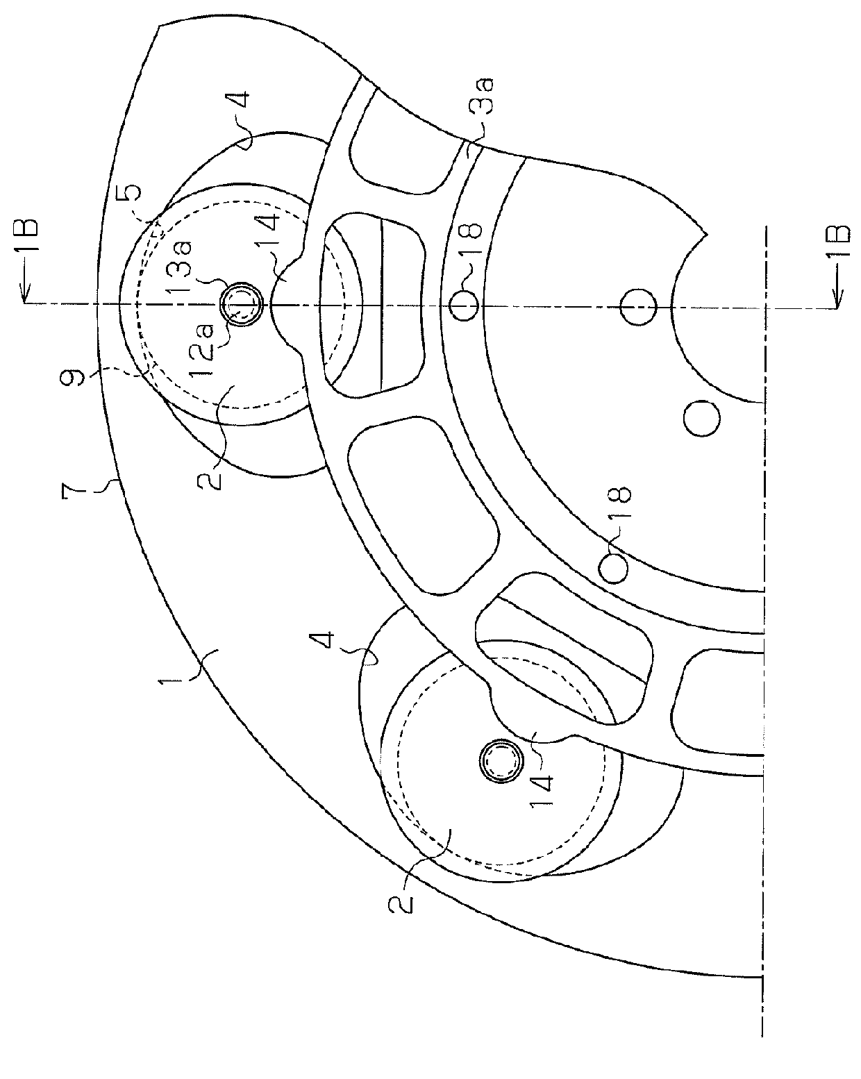
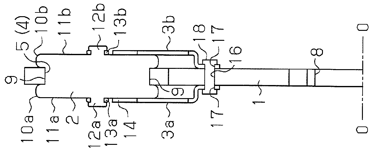
[0018]A dynamic vibration absorber according to one embodiment of the present invention will now be described with reference to FIGS. 1A to 4.

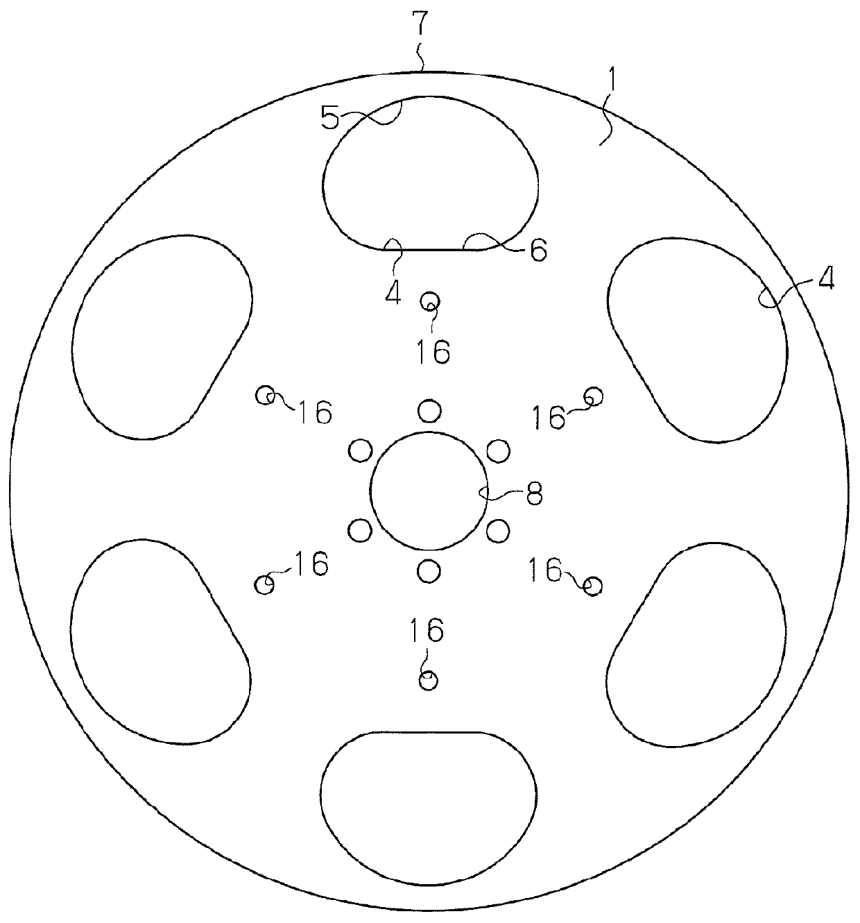
[0019]As shown in FIGS. 1A and 2, the dynamic vibration absorber includes a disk-like main body 1, rollers 2, and a pair of guide plates 3a, 3b. Six rolling element bores 4 are formed in the outer circumferential portion of the disk-like main body 1. The rolling element bores 4 are arranged at equal angular intervals around the center of the disk-like main body 1. The rolling element bores 4 have a generally elliptical shape.

[0020]Each rolling element bore 4 has an outer rim 5 and an inner rim 6 having different shapes. The radius of curvature of the outer rim 5 is set smaller than the radius of curvature of the peripheral edge 7 of the disk-like main body 1. The outer rim 5 extends along an arc having a predetermined radius of curvature. The inner rim 6 extends along a curved line at both ends, and extends otherwise along a straight line.

[002...


PUM

PropertyMeasurementUnit
torqueaaaaaaaaaa
circumferenceaaaaaaaaaa
diameteraaaaaaaaaa

Abstract

Rolling element bores are provided in the outer circumferential portion of a disk-like main body. Each rolling element bore has an arcuate outer rim. Rollers each have a groove formed on the peripheral edge and extending along the entire circumference of the roller. The outer rim of each rolling element bore engages with the groove of the associated roller so that the roller is loosely fitted in the rolling element bore. Shafts are respectively formed on both sides of each roller. The shafts project from the center of the roller. An elastic ring is mounted on each shaft. Annular guide plates are respectively mounted on both sides of the disk-like main body so that the shafts of the rollers are supported by the guide plates.

Description

BACKGROUND OF THE INVENTION[0001]The present invention relates to a dynamic vibration absorber that reduces torsional vibration of a power transmission system caused in accordance with torque fluctuation of an automobile engine.[0002]Conventionally, in fields such as automobiles, dynamic vibration absorbers have been proposed for reducing torsional vibration that occurs in power transmission systems. The dynamic vibration absorbers are typically mounted on a flywheel portion coupled to the crankshaft of the engine. Circular rolling element chambers are formed in the flywheel main body on which the dynamic vibration absorber is mounted. A spherical or roller type rolling element is accommodated in each of the rolling element chambers. In the dynamic vibration absorber, when the flywheel main body is rotated, the rolling elements that resonate with a predetermined order of the torsional vibration of the power transmission system roll in the rolling element chambers. Accordingly, a dyn...

Claims


Application Information

Patent Timeline
Patent Type & Authority Applications(United States)
IPC IPC(8): F16F15/10B21J5/04F16F15/31
CPCF16F15/145Y10T74/2131Y10T74/2121
Inventor KINOSHITA, TOMONORITANAKA, KATSUNORIOGAWA, AKIYAMASHITA, NAOHISAYAMAGUCHI, MAKOTO
Owner AISIN AW INDUSTRIES CO LTD
Why Eureka
Try Eureka