Battery Tray for Vehicle and Method for Producing the Battery Tray

a battery tray and vehicle technology, applied in the direction of battery/cell propulsion, cell components, manufacturing tools, etc., can solve problems such as intrusion, and achieve the effects of preventing deformation of batteries, reducing production costs, and reducing production costs

Inactive Publication Date: 2012-09-06
BENTELER ALUMINUM SYST FRANCE
View PDF24 Cites 84 Cited by
  • Summary
  • Abstract
  • Description
  • Claims
  • Application Information

AI Technical Summary

Benefits of technology

[0008]Otherwise, when hitting a curb during car severe running conditions, the battery tray has to support large deformations due to the car energy and to prevent the batteries from deformation.
[0009]The battery tray has also to provide a watertight housing to the batteries. Therefore generation of cracks in the battery tray should be prevented to avoid in particular expositing rescuer and repairer to electrical shock and dangerous liquids.
[0010]The aim of the invention is also to improve the protection of the batteries in case of crash, to contribute to strengthen the structure of the vehicle in order to absorb the energy of the vehicle in case of crash and to reduce the weight and the cost of the battery tray.
[0011]The reduction of weight generates a reduction of the consumption of electric energy and therefore provides an extension of the driving range or enables a reduction of the electrical energy capacity which provides a cost reduction.
[0012]The invention also aims at reducing the cost in manufacturing, investment, environment and recycling.
[0013]Moreover, the invention aims at reducing the overall size of the battery tray, increasing the number of batteries contained in the tray, improving the isolation of the batteries from the surrounding (water, intrusion of impacting projections) and cooling the batteries.

Problems solved by technology

In case of crash, especially side crash, the structure of the vehicle has to support very large deformation which risks generating intrusion (due to components of the vehicle itself, other vehicle involved, on / off road fixed obstacles, .

Method used


Image

  • Battery Tray for Vehicle and Method for Producing the Battery Tray
  • Battery Tray for Vehicle and Method for Producing the Battery Tray
  • Battery Tray for Vehicle and Method for Producing the Battery Tray

Examples


Embodiment Construction

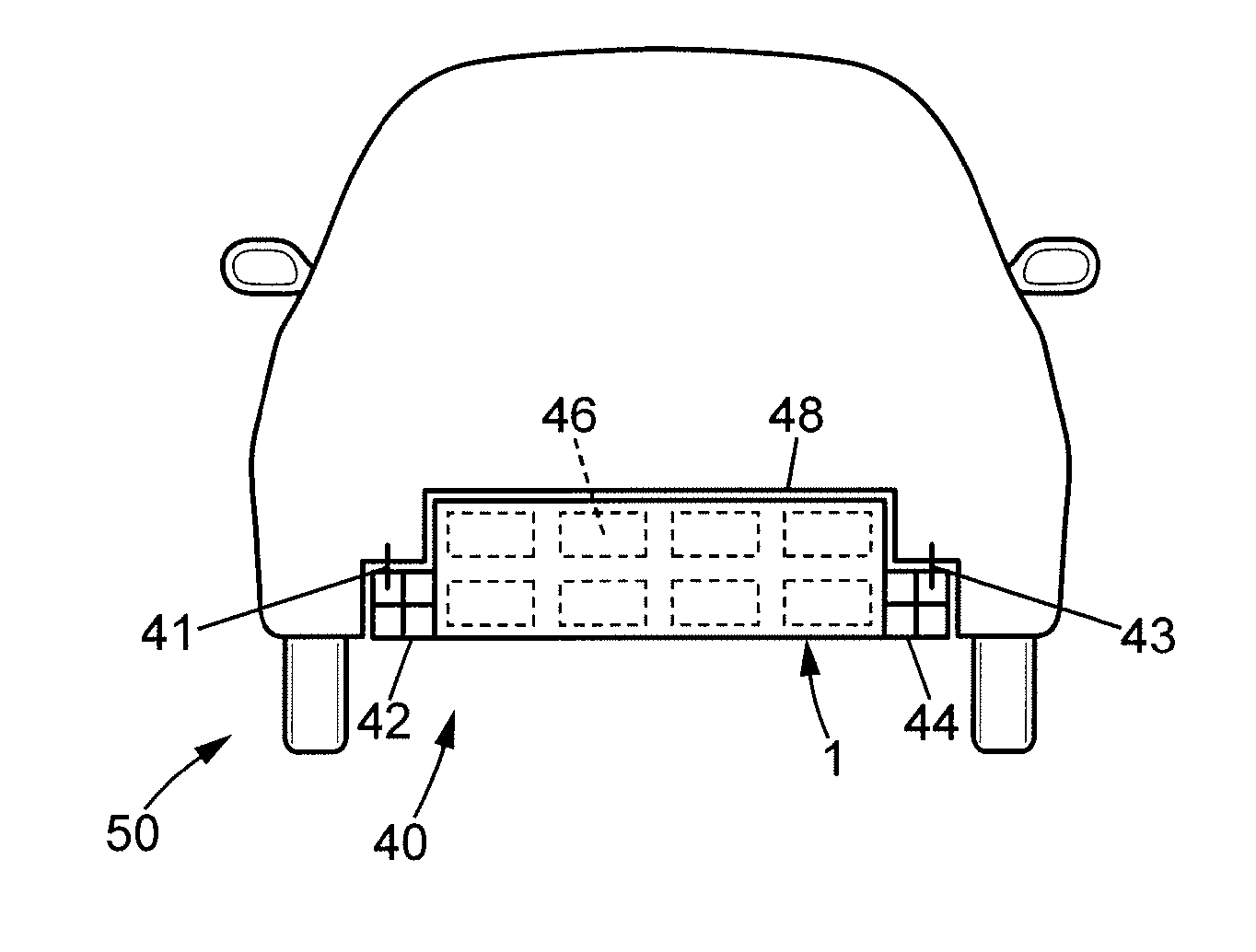
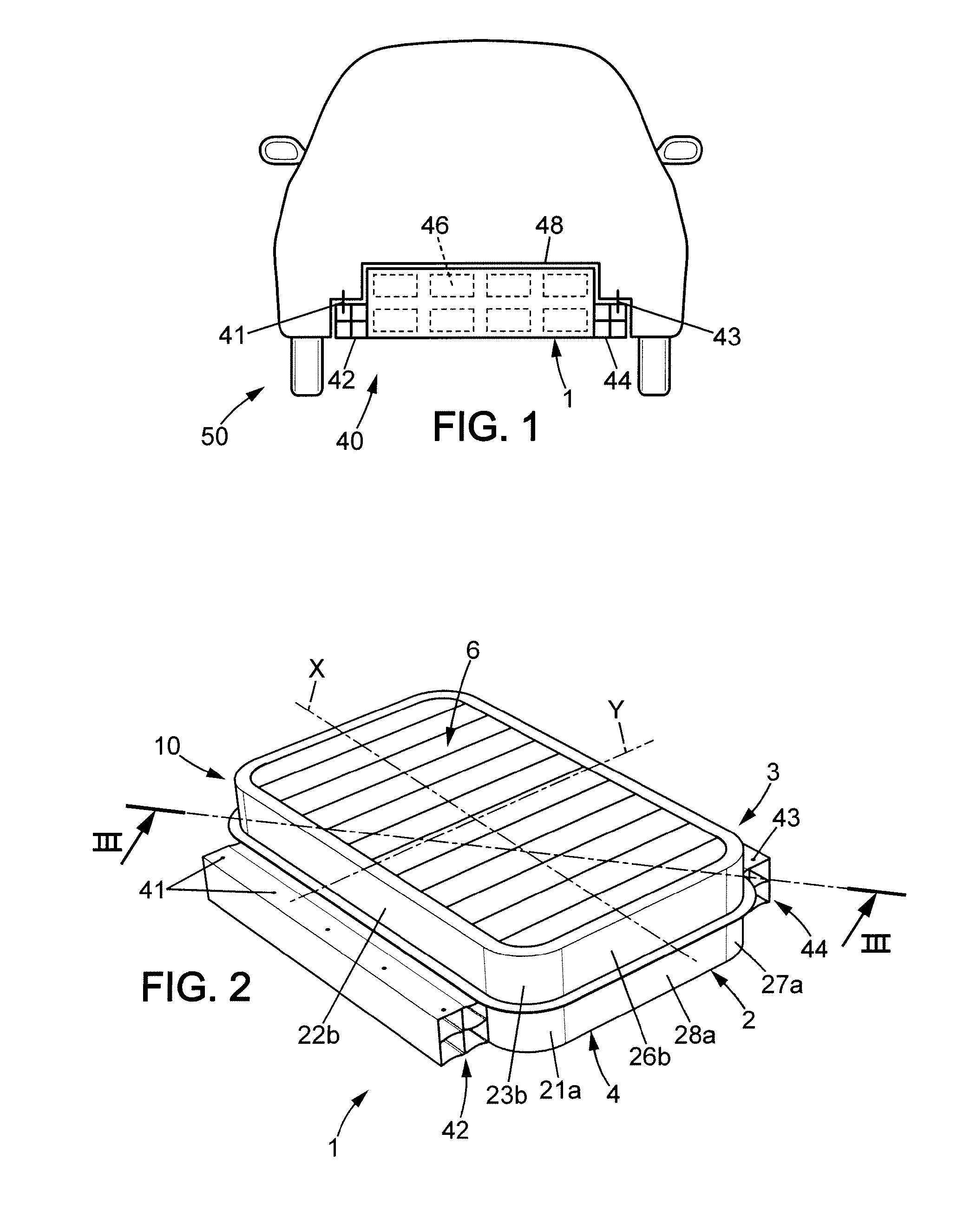
[0095]FIG. 1 shows a vehicle 50 having a structure, in particular a chassis 48, and an assembly 40 fixed to the structure 48. The assembly 40 comprises a battery tray 1 and two side members 42, 44. The battery tray 1 has a housing 8 containing batteries 46. Preferably, the housing is watertight and the battery tray has a structural function, constituting therefore a structural battery tray 1. The structural battery tray 1 is fixed to the chassis 48 of the vehicle 50 through the side members 42, 44.

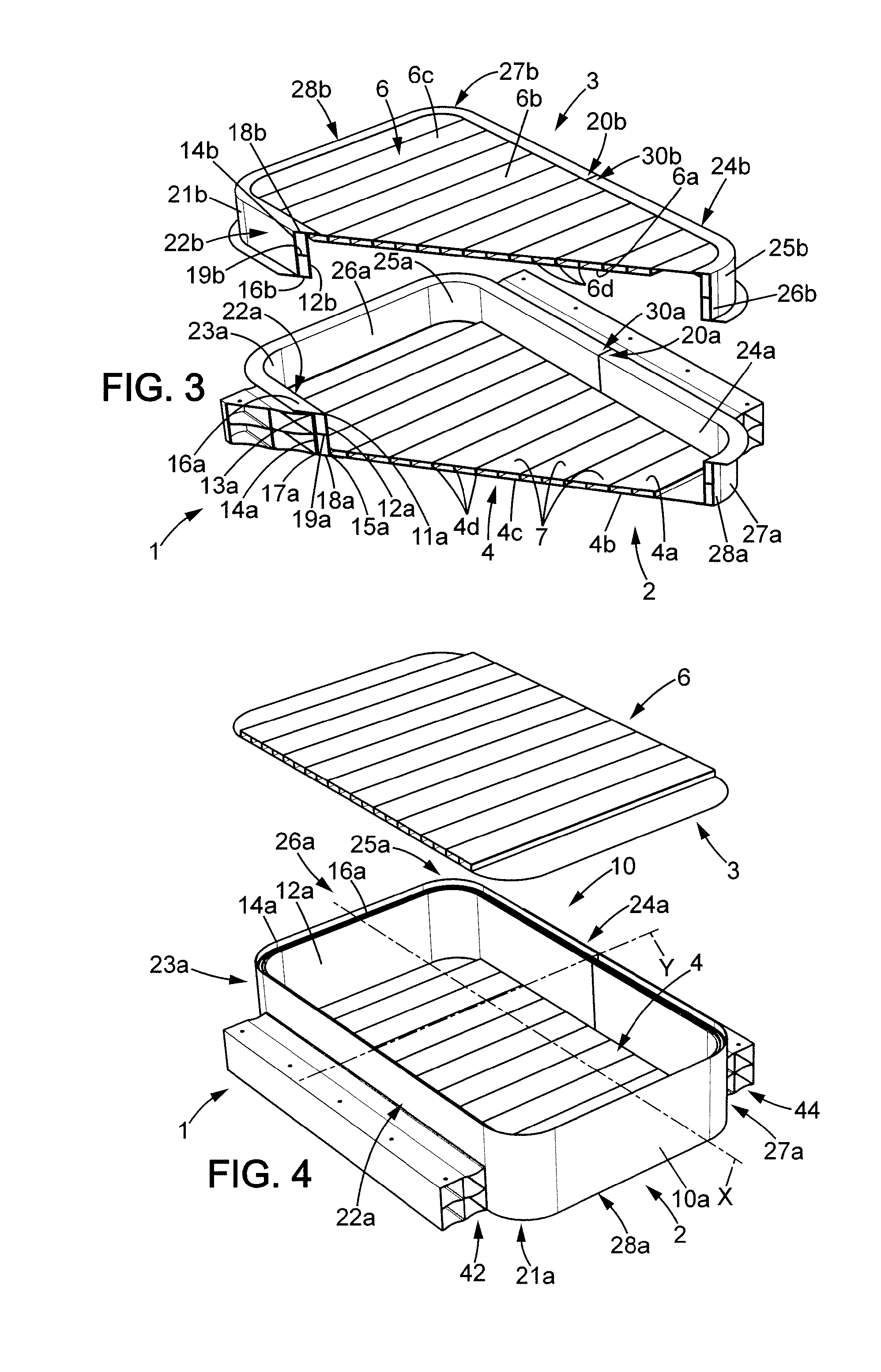
[0096]The FIG. 2 and the FIG. 3 show a first embodiment of the assembly 40. The structural battery tray 1 comprises a bucket 2 and a cover 3. The bucket 2 and the cover 3 define the housing 8 containing the batteries 46.

[0097]The bucket 2 comprises a first profile 10a and a floor 4 which is a (separate) part different from the first profile 10a and fixed on the first profile 10a. The main part of the bucket 2 consists in the first profile 10a constituting a first portion of a frame 10 of t...


PUM

PropertyMeasurementUnit
beveling angleaaaaaaaaaa
absorb energyaaaaaaaaaa
electrical energyaaaaaaaaaa

Abstract

Battery tray (1) for vehicle (50) comprising a closed frame (10), a floor (4) and a roof (6), wherein the frame (10), the floor (4) and the roof (6) define a housing (8) adapted to receive batteries, and the frame (10) comprises a profile (10a) having a substantially constant cross section. The profile (10a) comprises an internal wall (12a) delimiting the housing (8) and an external wall (14a) opposite the internal wall (12a), the internal wall (12a) and the external wall (14a) being spaced apart from each other.

Description

FIELD OF THE DISCLOSURE[0001]The invention relates to a battery tray for vehicle, a vehicle comprising the battery tray and a method for producing the battery tray.[0002]The battery tray is used for handling batteries into or under the vehicle body and may advantageously be removable to allow substitution of charged batteries for discharged batteries. The vehicle may be in particular a passenger car, especially an electrical car or an hybrid car.BACKGROUND OF THE DISCLOSURE[0003]In prior art, it was first proposed to dispose batteries containing the electrical energy into the passenger compartment. Afterwards, in order to increase the amount of electrical energy involved in the vehicle, and therefore increase the autonomy of the vehicle, it has been contemplated to place batteries into a battery tray outside the passenger compartment. Then such a compartment is exposed to severe conditions.[0004]It is already known a tray having a cast metal bucket and cast metal cover or a metal sh...

Claims


Application Information

Patent Timeline
Patent Type & Authority Applications(United States)
IPC IPC(8): B60R11/00B23P11/00B60L50/64
CPCH01M2/1083B60K1/04Y10T29/49826B60K2001/0438B60Y2306/01B62D29/008B60L53/80Y02T10/70Y02T10/7072Y02E60/10H01M50/249B60L50/64H01M50/278H01M50/276
Inventor GAISNE, DENISLECLERCQ, JEAN-PHILIPPE
Owner BENTELER ALUMINUM SYST FRANCE
Why Eureka
Try Eureka