Formwork Element

a technology of formwork and elements, applied in the direction of forming/stuttering elements, building parts, construction, etc., can solve the problem of high overall production cost, and achieve the effect of minimizing cleaning costs, minimizing cleaning costs, and maximizing the surface quality of concrete components

Inactive Publication Date: 2012-09-06
PERI GMBH
View PDF13 Cites 6 Cited by
  • Summary
  • Abstract
  • Description
  • Claims
  • Application Information

AI Technical Summary

Benefits of technology

[0021]In order to further optimize the surface quality of the concrete components to be produced and minimize the cleaning expense of the formwork element, the outer side of the formwork element or of the subsegments, which is designed as form lining, may additionally have a coating which counteracts adhesion of fresh or set concrete. This coating may, in particular, be a plastic coating or a powder coating.
[0022]In accordance with the invention, the formwork element has a width of less than 1000 mm, a thickness of 20 to 80 mm and a length of less than 4000 mm, advantageously of less than 3600 mm. In order to render handling particularly simple and safe with respect to weight and outer dimensions of the formwork element, it has turned out to be particularly advantageous in practice when the width of the formwork element does not exceed 600 mm.
[0023]The ribs or side walls of the hollow profile (subsegment) are inclined at an angle of less than 90° between the inner side and the outer side of the formwork element. The absorption of transverse forces can be further improved when the angles are between 30 and 70°. An angle of the ribs or side walls of approximately 45° with respect to the outer side is thereby particularly preferred, since the hollow profile can then be produced at very low cost and the intermediate segments or edge segments of this type can absorb the transverse forces acting on them without being deformed.

Problems solved by technology

For this work, the formwork elements must be available in different widths, for which reason the overall production costs are high.

Method used


Image

  • Formwork Element
  • Formwork Element
  • Formwork Element

Examples


Embodiment Construction

[0025]The invention is explained in more detail below with respect to embodiments with reference to the drawing.

[0026]In the drawing:

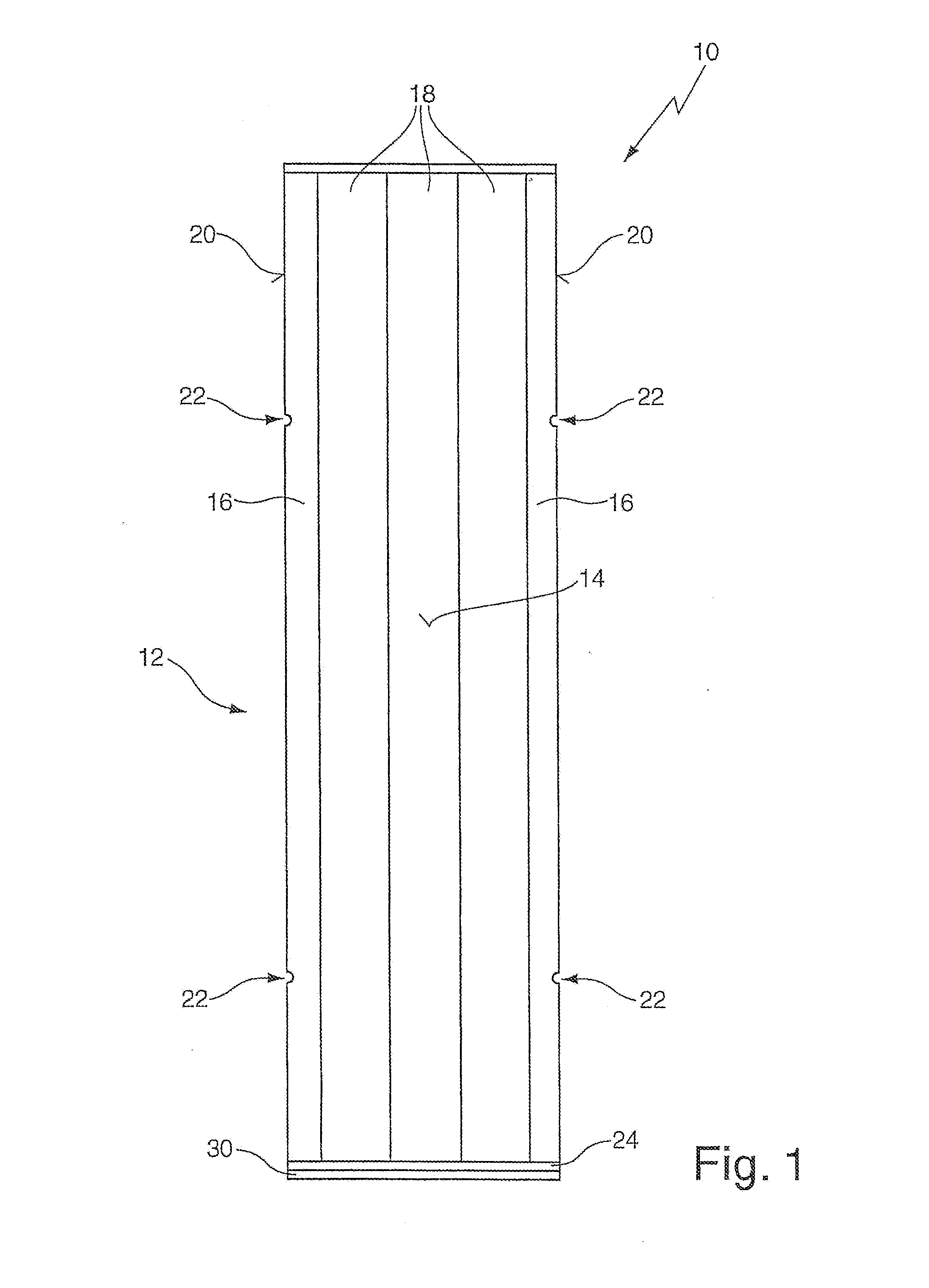
[0027]FIG. 1 shows a top view of a formwork element having a total of five subsegments which are connected to one another via an undetachable hook connection;

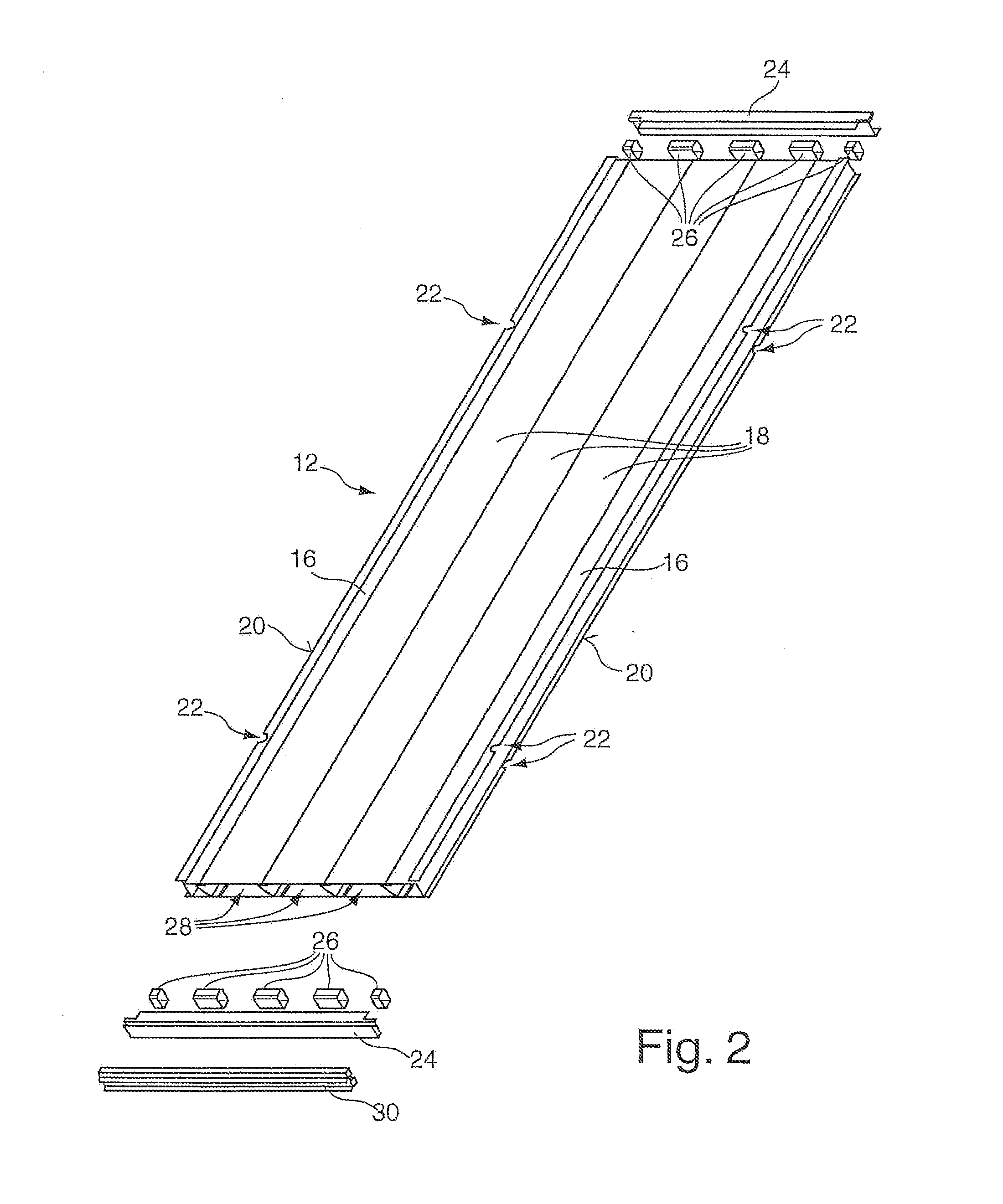
[0028]FIG. 2 shows a perspective exploded view of a formwork element in correspondence with FIG. 1;

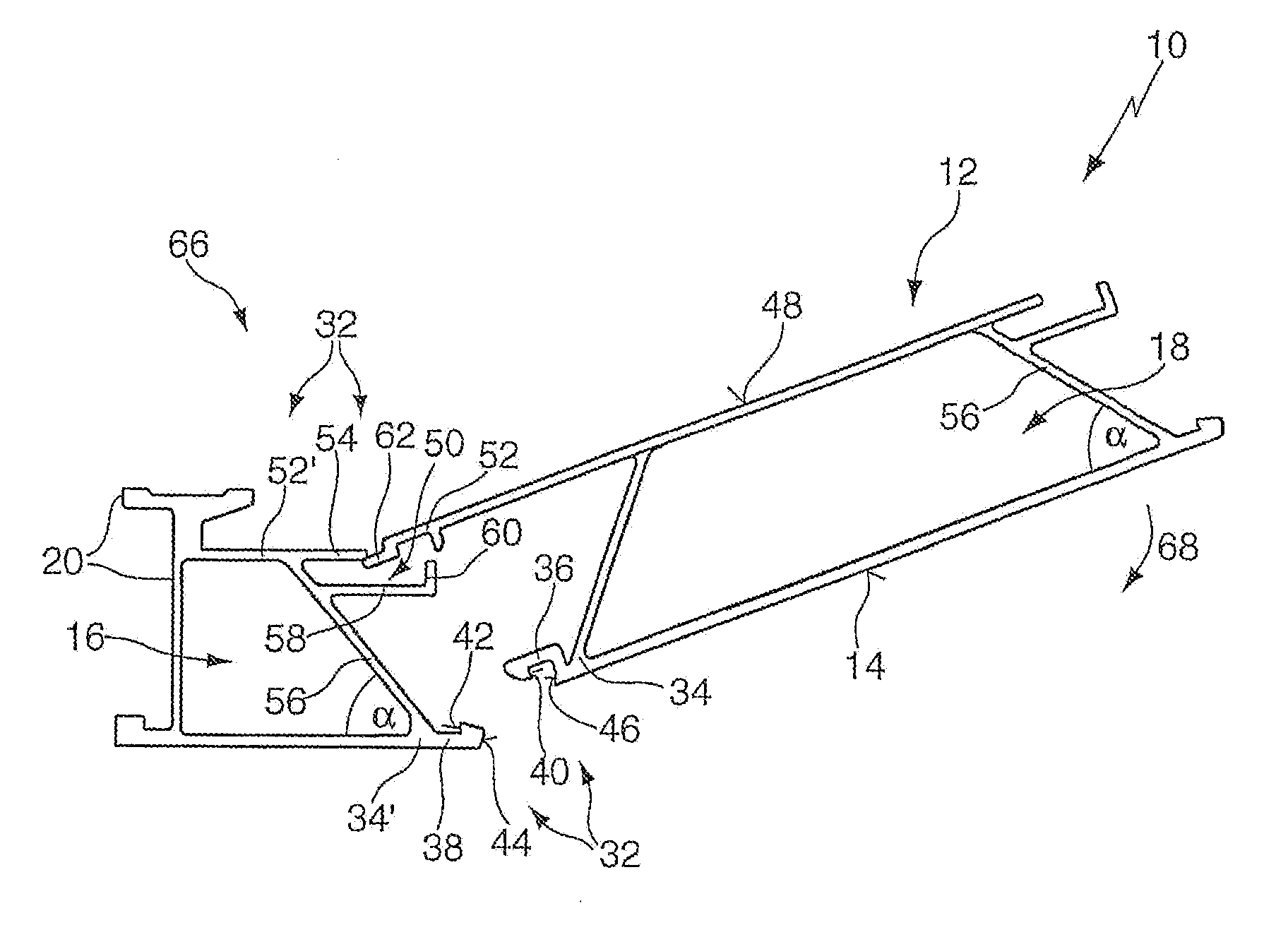
[0029]FIG. 3 shows a cross-section through a subsegment, designed as edge segment, and a joined subsegment, designed as intermediate profile, of a formwork element similar to FIG. 1;

[0030]FIGS. 4a-b show cross-sections through the subsegments shown in FIG. 3 during assembly thereof; and

[0031]FIGS. 5a-e show cross-sections through formwork elements similar to FIG. 1, each having a different width.

[0032]Corresponding components are suitably designated by the same reference numerals in the drawing. The views are highly schematic and not true to scale for a better understanding.

[0033]FIG. 1 shows a formw...


PUM

PropertyMeasurementUnit
thicknessaaaaaaaaaa
thicknessaaaaaaaaaa
lengthaaaaaaaaaa

Abstract

A formwork element 10 for concrete structures, has a base body 12 of hollow profile construction having an outer side 14 designed as a form lining. The base body 12 is formed by at least two interlocking subsegments which are permanently connected to one another at their interlocking edge areas. The subsegments, such as edge segment and intermediate segment 16, 18, which are advantageously produced through extrusion, are advantageously hooked to one another to form an inseparable unit in the connected state.

Description

[0001]The present invention concerns a formwork element for concrete structures, comprising a base body of hollow profile construction, the outer side of which is designed as a form lining.PRIOR ART[0002]Formwork elements that are ready for use have a base body, on which, in general, further extension elements, such as e.g. sealing elements, are arranged, and are used for formwork into which fresh concrete is introduced for producing concrete components, such as e.g. walls, ceilings and the like. For this work, the formwork elements must be available in different widths, for which reason the overall production costs are high.[0003]It is the underlying purpose of the invention to further develop a formwork element of the above-mentioned type in such a way that it can be produced in an inexpensive fashion.Advantages of the Invention[0004]This object is achieved in accordance with the invention by a formwork element comprising the features of claim 1.[0005]In accordance with the invent...

Claims


Application Information

Patent Timeline
Patent Type & Authority Applications(United States)
IPC IPC(8): B29C33/00
CPCE04G9/06Y10T29/49627E04G17/04E04G17/001
Inventor SCHNEIDER, WERNERMEYER, ANDREAS
Owner PERI GMBH
Why Eureka
Try Eureka