Microstrip patch antenna including planar metamaterial and method of operating microstrip patch antenna including planar metamaterial

a microstrip patch and antenna technology, applied in slot antennas, antenna equipments with additional functions, antennas, etc., can solve the problems of difficult to commercialize the metamaterial antenna and difficult to use the antenna practically, and achieve the effect of wide bandwidth, miniaturization of antennas, and broadening bandwidth

Inactive Publication Date: 2012-09-06
ELECTRONICS & TELECOMM RES INST +1
View PDF4 Cites 48 Cited by
  • Summary
  • Abstract
  • Description
  • Claims
  • Application Information

AI Technical Summary

Benefits of technology

[0024]According to an embodiment of the present invention, a microstrip patch antenna may have an isotropic radiation pattern as well as a wide bandwidth and a miniaturized size, in an operating frequency band.
[0025]According to another embodiment of the present invention, a microstrip patch antenna may have an antenna configuration where a unit cell of a metamaterial, including a complementary split-ring resonator (CSRR) slot and an interdigital capacitor, may be inserted in the microstrip patch antenna.
[0026]According to another embodiment of the present invention, an antenna may be miniaturized and a bandwidth may be broadened by adjusting an operating frequency, by inserting a configuration of a unit cell of a metamaterial in a microstrip patch antenna, and by adjusting a length of an inserted interdigital capacitor.
[0027]According to another embodiment of the present invention, an antenna may be miniaturized by changing an operating frequency of the antenna, by matching impedance of the antenna by adjusting a size with respect to any of a radius, a width, a ring gap, and a ring split of the CSRR, thereby miniaturizing the antenna.
[0028]According to another embodiment of the present invention, an optimal impedance matching may be induced, by supporting a flexible adjustment of parameter values of a patch and a CSRR slot, with respect to multiple resonances caused by a characteristic of an inserted metamaterial.

Problems solved by technology

However, it may be difficult to commercialize the developed metamaterial antenna due to a complex manufacturing process, a narrow bandwidth, a low gain, and the like.
Also, although antenna technologies have been developed to improve the aforementioned factors, it may also be difficult to use the antenna practically due to distortion of a radiation pattern.

Method used


Image

  • Microstrip patch antenna including planar metamaterial and method of operating microstrip patch antenna including planar metamaterial
  • Microstrip patch antenna including planar metamaterial and method of operating microstrip patch antenna including planar metamaterial
  • Microstrip patch antenna including planar metamaterial and method of operating microstrip patch antenna including planar metamaterial

Examples


Embodiment Construction

[0042]Reference will now be made in detail to exemplary embodiments of the present invention, examples of which are illustrated in the accompanying drawings, wherein like reference numerals refer to the like elements throughout. Exemplary embodiments are described below to explain the present invention by referring to the figures.

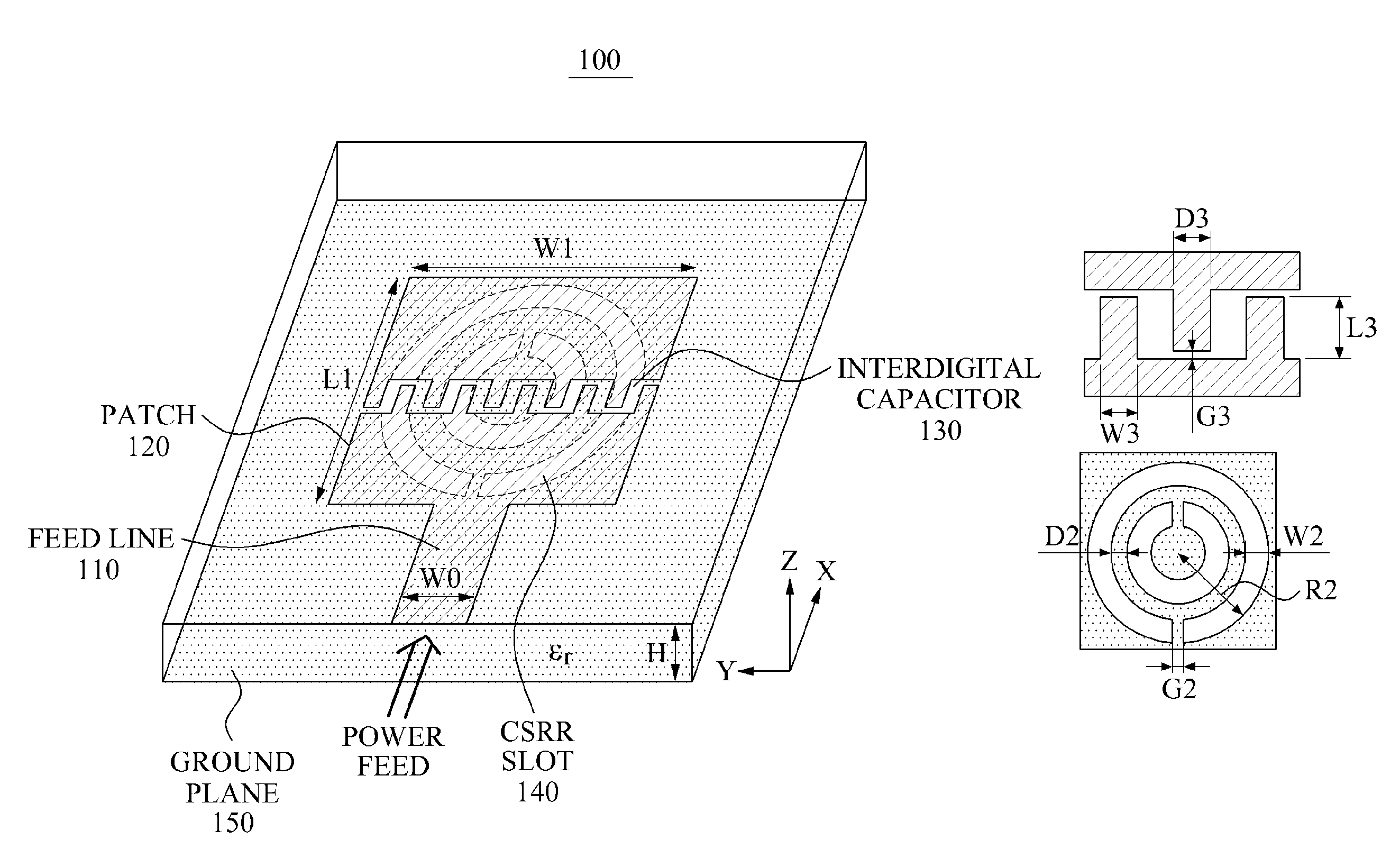
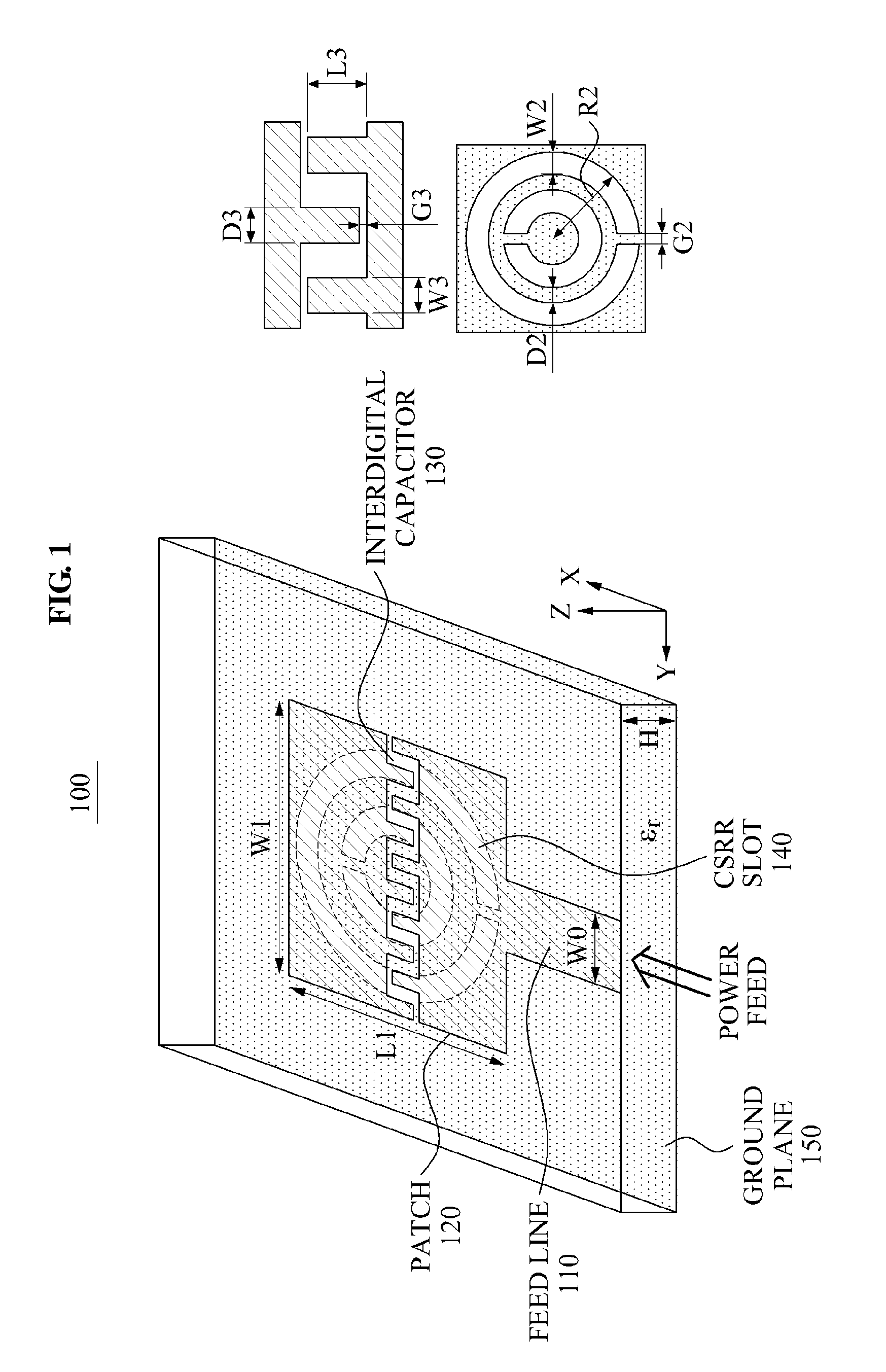
[0043]FIG. 1 illustrates a configuration of a microstrip patch antenna 100 according to an embodiment of the present invention.

[0044]Referring to FIG. 1, the microstrip patch antenna 100, which will be hereinafter referred to as an ‘antenna’ may include a microstrip feed line 110, a patch 120, an interdigital capacitor 130, a complementary split-ring resonator (CSRR) slot 140, and a ground plane 150.

[0045]On an upper surface of a dielectric substrate, the patch 120, which may be conductive and in which the microstrip feed line 110 and the interdigital capacitor 130 may be inserted, may be included. The patch 120 may adjust an electrical size of the antenna ...


PUM


Abstract

Provided is a microstrip patch antenna in which a unit cell of a planar metamaterial may be inserted to have a miniaturized size, a wide bandwidth, or multi-resonance.

Description

CROSS-REFERENCE TO RELATED APPLICATION[0001]This application claims the benefit of Korean Patent Application No. 10-2011-0018336, filed on Mar. 2, 2011, in the Korean Intellectual Property Office, the disclosure of which is incorporated herein by reference.BACKGROUND[0002]1. Field of the Invention[0003]The present invention relates to a technology that may miniaturize an antenna and may extend a bandwidth, by greatly reducing a resonance frequency of the antenna.[0004]2. Description of the Related Art[0005]In early research, an antenna that may be operated in a zeroth-order resonance mode was developed using a unit cell of a metamaterial including a gap and a via hole, to have a resonance frequency independent of a size of the antenna.[0006]A technology has currently reached a stage of miniaturizing the size of the antenna and configuring the antenna in a planar form, using a metal-insulator-metal (MTM) capacitor, a virtual ground inductor, and the like. Also, a broadband and a high...

Claims


Application Information

Patent Timeline
Patent Type & Authority Applications(United States)
IPC IPC(8): H01Q13/12H01Q5/01H01Q5/10H01Q5/314
CPCH01Q9/0442H01Q5/314H01Q15/0086H01Q13/08H01Q1/46H01Q5/00
Inventor KIM, DONG HOHA, JAE GEUNLEE, YOUNG KILEE, YOUNG SUNGCHOI, JAE HOON
Owner ELECTRONICS & TELECOMM RES INST
Why Eureka
Try Eureka