
Multi pulse linear ionizer

Active Publication Date: 2012-09-06
ILLINOIS TOOL WORKS INC
View PDF2 Cites 33 Cited by
  • Summary
  • Abstract
  • Description
  • Claims
  • Application Information

AI Technical Summary

Benefits of technology

[0010]An embodiment of the invention provides an air / gas ionizing apparatus and method that produce both positive and negative ions for reducing electrostatic charges on various objects. Embodiments of the invention may achieve one or more of the following possible advantages:
[0012](2) Reducing the buildup of particles on the emitter points or wire electrodes and minimizing the contamination associated with corona discharge particle emission from the ionizing bar;
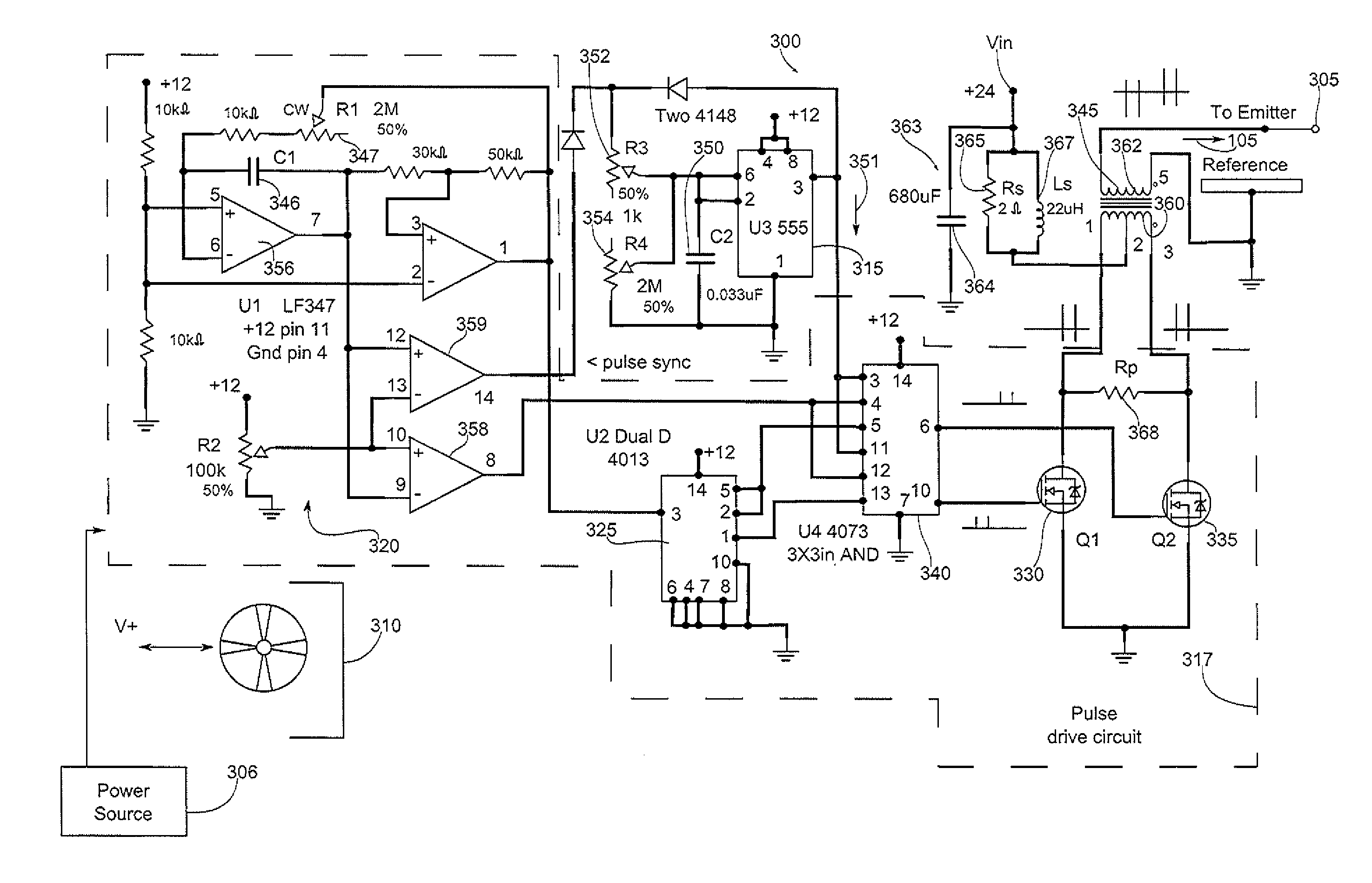
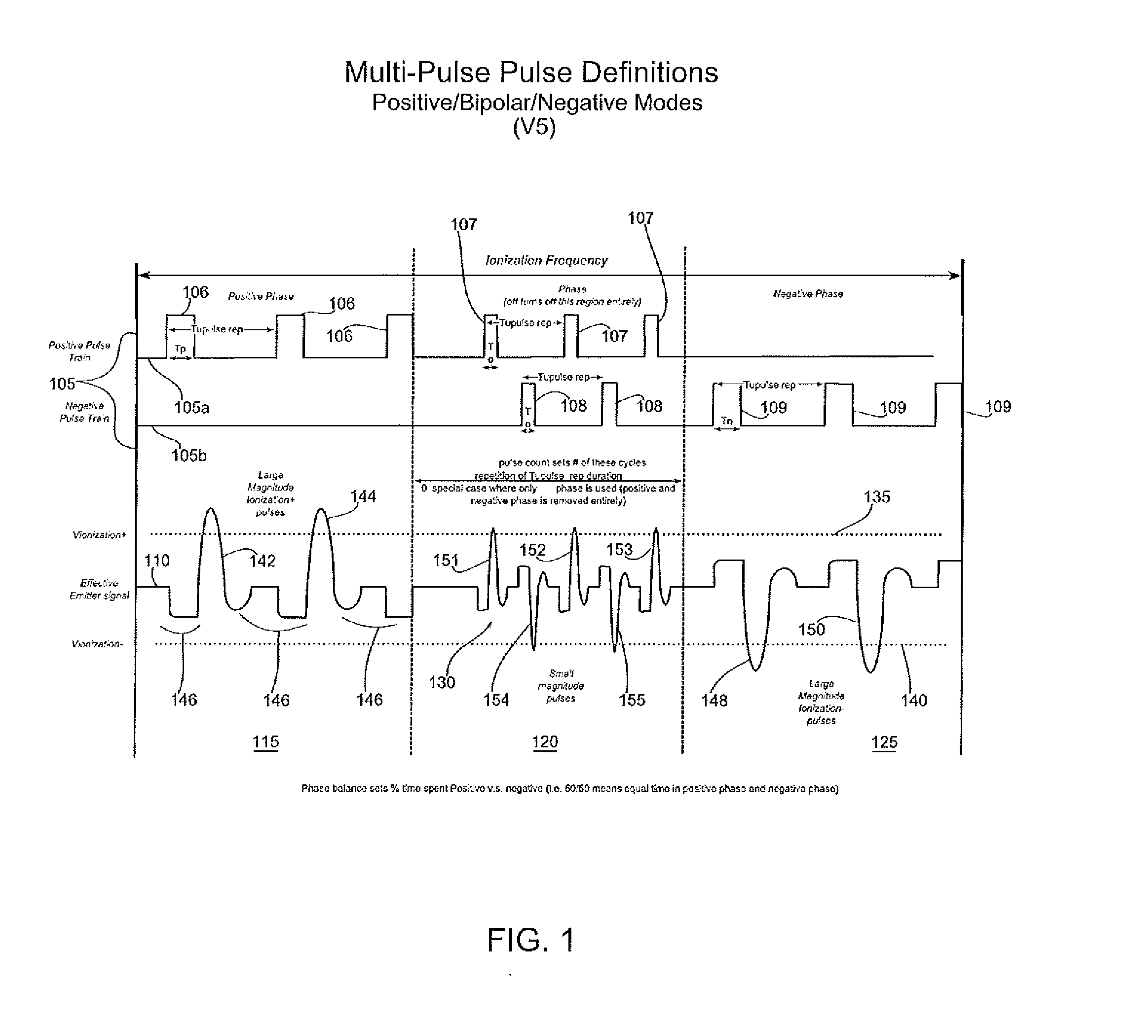
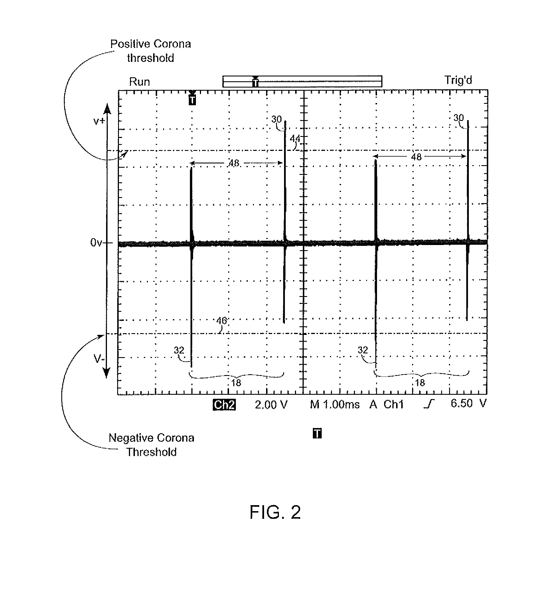
[0015]In one particular embodiment of the invention, the high voltage applied to the points or the wire electrode is designed to be of very low power and high ionization efficiency. This is accomplished by using very strong, micro-second wide pulses at a very low rate. A flyback type generator produces such waves naturally in a resonant circuit. Each wave includes at least three voltage peaks: a beginning low amplitude peak, a second high amplitude peak of opposite polarity, and a final low amplitude peak (wave). Typically, only the high level wave is used for ionization. The first wave and third wave can be reduced greatly in amplitude by a proper damping, as explained later. The use of such low power reduces ozone generation, corona byproduct production, collection and shedding of particles, and wear of the emitters.

Problems solved by technology

However, these ionizers are prone to a relatively high ozone emission and higher rate of electrode contamination by collecting debris from the surrounding air.
Electrode contamination decreases the ionization efficiency and may affect ion balance.

Method used


Image

  • Multi pulse linear ionizer
  • Multi pulse linear ionizer
  • Multi pulse linear ionizer

Examples


Embodiment Construction

[0032]In the following detailed description, for purposes of explanation, numerous specific details are set forth to provide a thorough understanding of the various embodiments of the present invention. Those of ordinary skill in the art will realize that these various embodiments of the present invention are illustrative only and are not intended to be limiting in any way. Other embodiments of the present invention will readily suggest themselves to such skilled persons having benefit of the herein disclosure.

[0033]An embodiment of the present invention can apply to many types of air-gas ionizers configured as ionizing bars, blowers, or in-line ionization devices.

[0034]Pulse mode ionizers are known in the art. For example, patent application publications JP2008124035, US 20060151465, and US 20090116828 describe AC ionizing bars. U.S. Pat. No. 8,009,405 discloses a design of ionizing blowers with high voltage power supplies generating periodically burst of positive and negative puls...


PUM


Abstract

An embodiment of the invention provides a method for generating ions within a space separating an emitter and a reference electrode, the method comprising: generating a variable number of small sharp pulses and rate of the pulses depending on the distance of the target from the emitter.

Description

CROSS-REFERENCE TO RELATED APPLICATIONS[0001]This application is a continuation-in-part of U.S. application Ser. No. 13 / 210,267, filed 15 Aug. 2011, which is a continuation of U.S. application Ser. No. 12 / 049,350, filed 16 Mar. 2008 and issued as U.S. Pat. No. 8,009,405, which claims the benefit of and priority to U.S. Provisional Application No. 60 / 918,512, filed 17 Mar. 2007.[0002]This application also claims the benefit of and priority to U.S. Provisional Application No. 61 / 584,173, filed 6 Jan. 2012.[0003]This Application is also a continuation-in-part of U.S. application Ser. No. 13 / 023,397, filed 8 Feb. 2011.[0004]Applications Ser. Nos. 13 / 210,267, 12 / 049,350, 60 / 918,512, 61 / 584,173, and 13 / 023,397 are hereby incorporated herein by reference.BACKGROUND OF THE INVENTION[0005]1. Field of the Invention[0006]This invention relates to AC corona ionizers for both positive and negative static charges neutralization. More particularly, this invention is relates to AC corona ionizers w...

Claims


Application Information

Patent Timeline
IPC IPC(8): H01T23/00
CPCH01T23/00
Inventor PARTRIDGE, LESLIEGEFTER, PETEROLDYNSKI, EDWARD
Owner ILLINOIS TOOL WORKS INC
Learn More