System, Method, and Apparatus for High-Sensitivity Optical Detection

Active Publication Date: 2012-09-06
LGS INNOVATIONS
View PDF5 Cites 26 Cited by
  • Summary
  • Abstract
  • Description
  • Claims
  • Application Information

AI Technical Summary

Benefits of technology

[0009]In one embodiment, the additional modulation of the pulse/s is through polarization-division-multiplexed quadrature-phase-shift keying (PDM-QPSK), and the new format is hereafter referred to as PQ-mPPM (Polarization-division-multiplexed Quadrature-phase-shift-keyed m-ary-Pulse-Position-Modulation). The coherent detection of the PQ-mPPM signal may be based on pil

Problems solved by technology

When used with ideal photon-counting receivers, m-PPM is capable of approaching the Shannon limit with the increase of m. However, photon-counting receivers currently have limited ba

Method used


Image

  • System, Method, and Apparatus for High-Sensitivity Optical Detection
  • System, Method, and Apparatus for High-Sensitivity Optical Detection
  • System, Method, and Apparatus for High-Sensitivity Optical Detection

Examples


Embodiment Construction

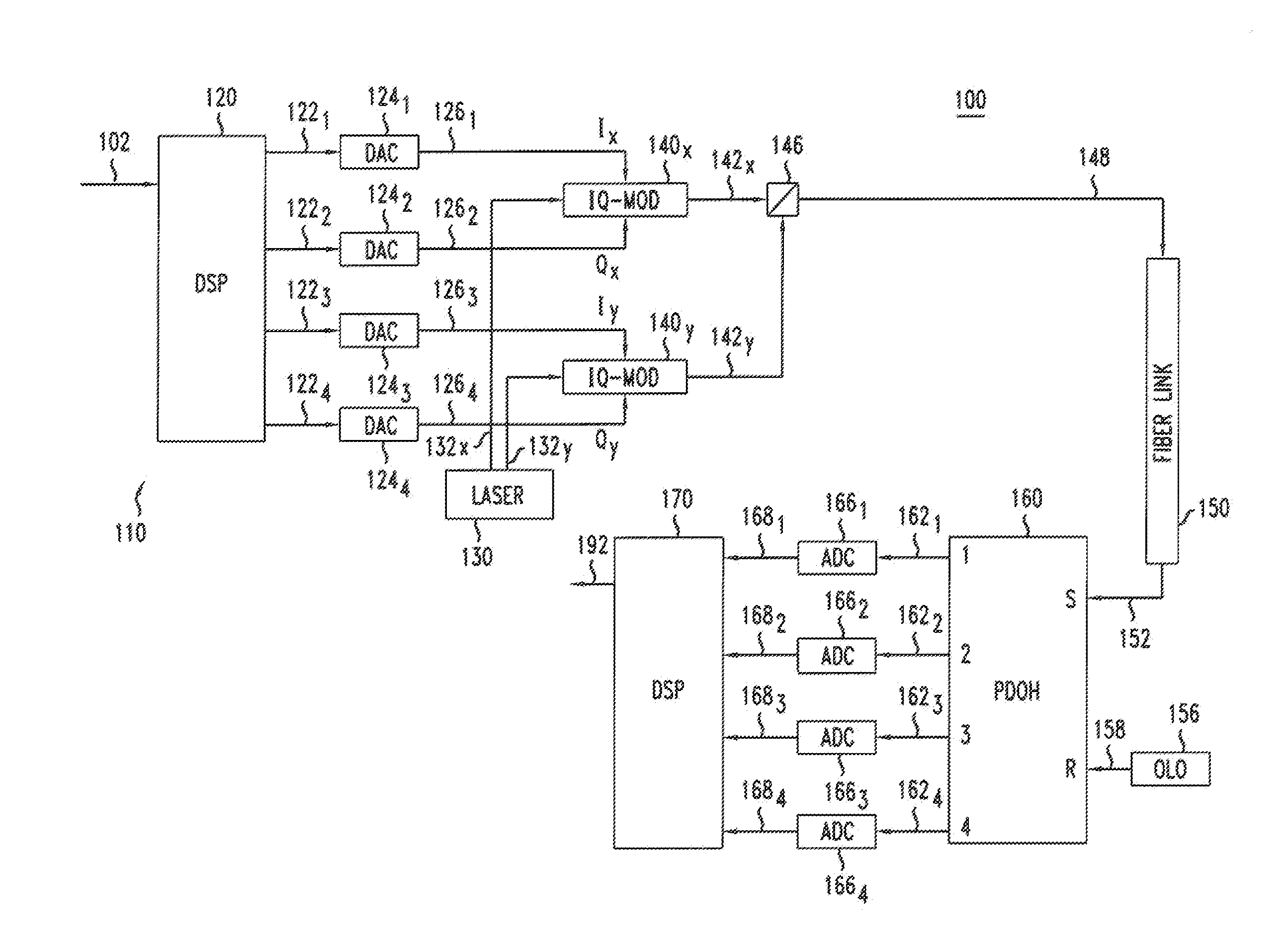
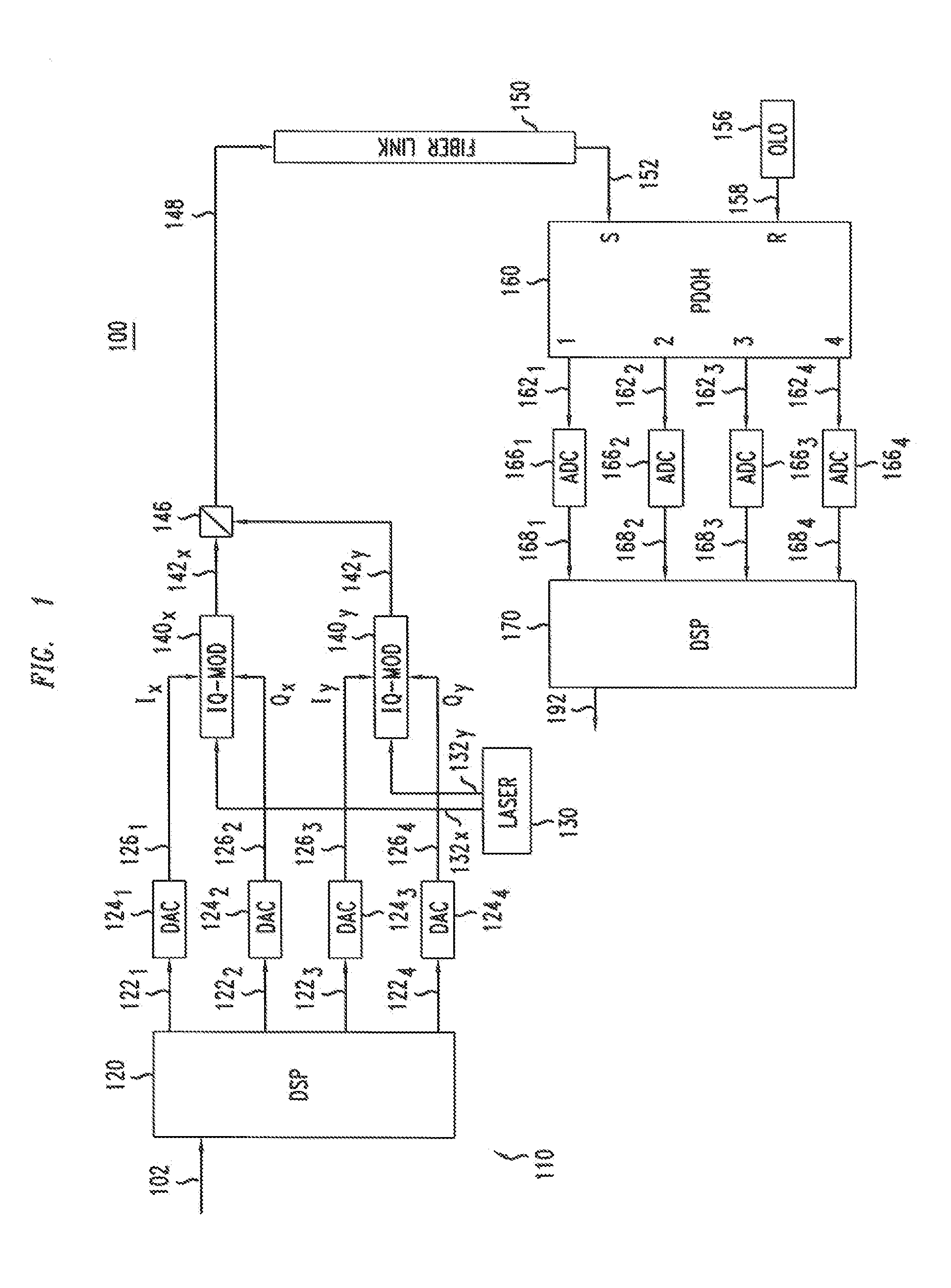
[0039]FIG. 1 shows a block diagram of an optical transmission system 100 according to one embodiment. System 100 has an optical transmitter 110 and an optical receiver 190 connected via a transmission link 150. In one embodiment, transmission link 150 is a free-space optical link, e.g., a link connecting a satellite and a ground station (not explicitly shown in FIG. 1). In another embodiment, transmission link 150 is an amplified fiber link having one or more optical amplifiers (not explicitly shown in FIG. 1).

[0040]Transmitter 100 receives an input data stream 102 for transmission to receiver 190. A digital-signal processor 120 processes data stream 102 as further described below in reference to FIGS. 2, 3, 4 and 5 to generate digital signals 1221-1224. Digital signals 1221-1224 undergo a digital-to-analog conversion in digital-to-analog converters (DACs) 1241-1244, respectively, to produce drive signals 1261-1264. Drive signals 1261 and 1262 are in-phase (I) and quadrature-phase (...


PUM


Abstract

An apparatus transmits data using a format where information bits intended for transmission are mapped into symbols each carrying a plurality of bits, some of which are encoded through pulse position modulation (PPM) format and the rest of which are encoded through an additional modulation format on each PPM pulse. The additional modulation format for the PPM pulse may be at least one of a polarization-division-multiplexed (PDM) modulation, phase-shift keying (PSK) modulation, polarization shift keying (PolSK) modulation, amplitude modulation (AM), quadrature-amplitude modulation (QAM) modulation, or a combination thereof. In one embodiment, the additional modulation of the PPM pulses is through polarization-division-multiplexed quadrature-phase-shift keying (PDM-QPSK). The unique combined use of PDM-QPSK and PPM produces much higher receiver sensitivity than either PPM or PDM-QPSK alone.

Description

CROSS-REFERENCE TO RELATED APPLICATIONS[0001]The subject matter of this application is related to that of U.S. patent application Ser. No. 1______, by Xiang Liu, Robert William Tkach, and Thomas Huntington Wood, attorney docket reference 809324-US-NP, filed on the same date as the present application, and entitled “System, Method and Apparatus for High-Sensitivity Optical Detection,” which application is incorporated herein by reference in its entirety.BACKGROUND[0002]1. Field of the Invention[0003]The present invention relates to optical communication equipment and, more specifically but not exclusively, to optical modulation and detection in coherent optical transmission systems.[0004]2. Description of the Related Art[0005]This section introduces aspects that may help facilitate a better understanding. Accordingly, the statements of this section are to be read in this light and are not to be understood as admissions about what is in the prior art or what is not in the prior art.[0...

Claims


Application Information

Patent Timeline
IPC IPC(8): H04B10/04H04J14/06
CPCH04B10/2507H04B10/5161H04L27/3483H04B10/616H04L25/4902H04B10/524H04L25/49
Inventor LIU, XIANGWOOD, THOMAS HUNTINGTONTKACH, ROBERT WILLIAM
Owner LGS INNOVATIONS
Why Eureka
Try Eureka