Centrifugal wet gas compression or expansion with a slug suppressor and/or atomizer

a technology of centrifugal wet gas and suppressor, which is applied in the direction of machines/engines, liquid fuel engines, positive displacement liquid engines, etc., can solve the problems of slugging compressor or expander equipment, limited range, and fraction of one percent liquid, so as to improve the upstream mixing of liquid and improve the effect of handling higher levels of liquid

Inactive Publication Date: 2012-09-06
UPTIGROVE STANLEY O
View PDF8 Cites 19 Cited by
  • Summary
  • Abstract
  • Description
  • Claims
  • Application Information

AI Technical Summary

Benefits of technology

[0010]The above noted problems in handling multiphase fluid flow have been addressed by utilizing a liquid slug suppressor and / or an atomizing device to enhance the upstream mixing of the liquid with the gas, thus enabling the centrifugal compressor or expander to better handle higher levels of liquid. The atomizing device may be any one of known fluid atomizers including one or more atomizing nozzles or a flow mixer device. This can be used in existing designs to help protect the compressor or expander from process upsets with additional liquid volume or as a stand alone design to help eliminate some of the required equipment such as the separator or liquid pump.

Problems solved by technology

Traditionally it is understood that centrifugal compressors or gas expanders do not handle liquid slugs and thus it is assumed that they can only handle a fraction of one percent liquid by volume.
Thus in many applications expensive liquid separators, dehydration processes and / or unit scrubbers are utilized to try and remove or separate the liquids prior to using centrifugal compressors or expanders.
These devices are often designed for specific operating conditions and are then limited in the range of Gas Volume Fraction (GVF) that can be handled with a given process flow rate.
Even with this expensive and complex processing equipment, if there is a sudden high level of liquids they can quickly saturate, fill and overflow the liquid separators once their capacity for liquid is exceeded resulting in slugging the compressor or expander equipment.
Centrifugal compressors are often restricted to applications with GVFs of 99.7 or higher and even this can cause problems within the machine for stability and affecting the reliability of the seals and bearings.
Therefore, for processes outside this small range, the current practice is to separate the fluids prior to utilizing a centrifugal compressor even with the design limitation with the associated process and equipment.
The separators, scrubbers and dehydration units are not only expensive and limited in liquid capacity and volume flow range but they also tend to be very bulky, taking up expensive real estate in locations such as offshore platforms, subsea processing or onshore facilities.
This coupled with complex control systems and additional auxiliary equipment like pumps, regulators, level controllers, transmitters and filters adds to the complexity and likelihood of failure of these systems.
Some additional issues with liquids are not only stability of the machine but also erosion of impellers and diffusers, fouling and resulting in imbalance if the liquids flash or vaporize while being compressed in the machine.

Method used


Image

  • Centrifugal wet gas compression or expansion with a slug suppressor and/or atomizer
  • Centrifugal wet gas compression or expansion with a slug suppressor and/or atomizer
  • Centrifugal wet gas compression or expansion with a slug suppressor and/or atomizer

Examples


embodiment e

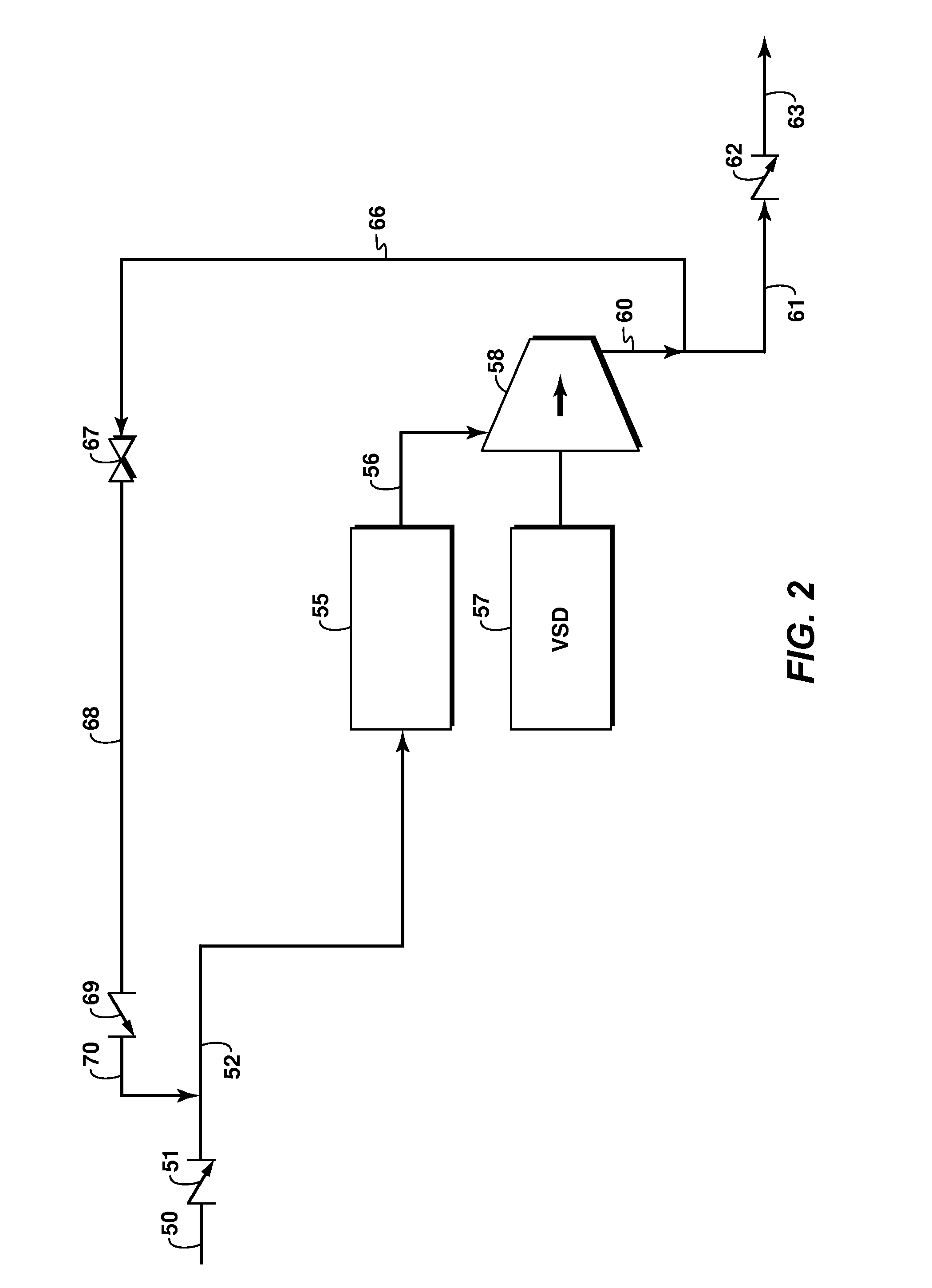
[0040] The apparatus of any of embodiments A-D, further comprising a means for controlling the compressor speed based on produced torque, load, fluid density, multiphase flow measurement or output power.

embodiment f

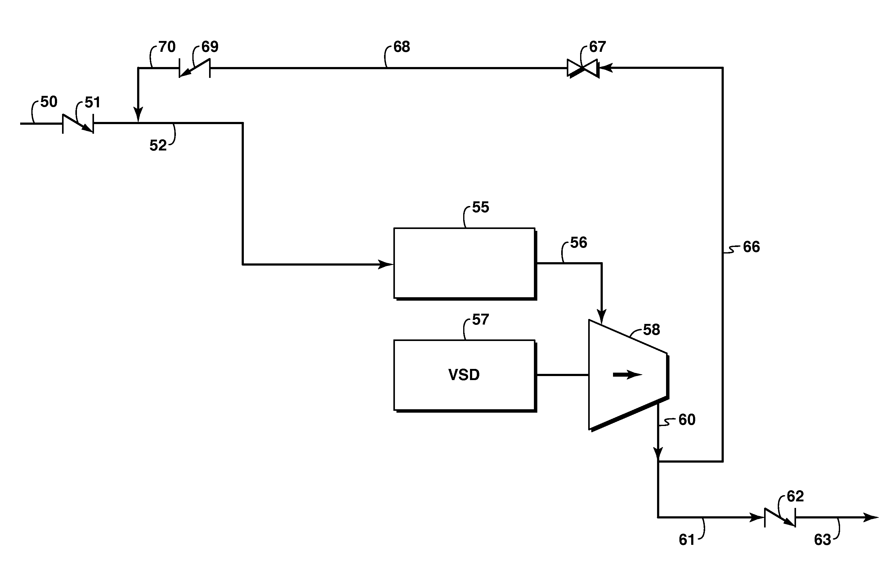
[0041] The apparatus of embodiment B or C, wherein the slug suppressor and atomizing device are combined in a housing having an inlet and outlet, wherein the housing comprises:

[0042]a first chamber for accumulating liquid;

[0043]a second chamber for accumulating gas;[0044]a plurality of baffles between the first and second chambers for allowing accumulated liquid in the first chamber to spill over into the second chamber; and

[0045]a plurality of atomizing nozzles located at the end portion of the first chamber.

[0046]Embodiment G: Apparatus according to embodiment F, wherein the housing tapers from the inlet to the outlet.

embodiment

[0047 H: Apparatus according to any of embodiments A-G, further comprising a recycle conduit connected at one end to the output of the compressor and at its other end to the first conduit.


PUM


Abstract

This disclosure is to an apparatus and method for increasing the ability of centrifugal compressors or expanders to handle multiphase fluids with increased liquid content by passing the fluid through a slug suppressor and/or an atomizing device prior to compression or expansion.

Description

CROSS-REFERENCE TO RELATED APPLICATION[0001]This application claims the benefit of U.S. Provisional Patent Application 61 / 264,414 filed 25 Nov. 2009 entitled CENTRIFUGAL WET GAS COMPRESSION OR EXPANSION WITH A SLUG SUPPRESSOR AND / OR ATOMIZER, the entirety of which is incorporated by reference herein.BACKGROUND OF INVENTION[0002]1. Field of the Invention[0003]The subject matter disclosed in this application relates to technology utilized in the compression or expansion of a multiphase fluid in a fluid handling system.[0004]2. Description of Related Art[0005]This section is intended to introduce various aspects of the art, which may be associated with exemplary embodiments of the present invention. This discussion is believed to assist in providing a framework to facilitate a better understanding of particular aspects of the present invention. Accordingly, it should be understood that this section should be read in this light, and not necessarily as admissions of prior art.[0006]Tradi...

Claims


Application Information

Patent Timeline
Patent Type & Authority Applications(United States)
IPC IPC(8): F04B23/14F04B53/00
CPCF04D31/00F04D29/5846
Inventor UPTIGROVE, STANLEY O.
Owner UPTIGROVE STANLEY O
Why Eureka
Try Eureka