Proppant Particles Formed From Slurry Droplets and Method of Use

Active Publication Date: 2012-09-13
CARBO CERAMICS
View PDF16 Cites 104 Cited by
  • Summary
  • Abstract
  • Description
  • Claims
  • Application Information

AI Technical Summary

Problems solved by technology

As wells became deeper, sand was found to have inadequate strength.
In deep wells, stress of the earth causes the sand to crush and become much less effective in increasing the production rate of a well.
The pellet-forming methods described above have intrinsic limitations.
These processes require

Method used


Image

  • Proppant Particles Formed From Slurry Droplets and Method of Use
  • Proppant Particles Formed From Slurry Droplets and Method of Use
  • Proppant Particles Formed From Slurry Droplets and Method of Use

Examples


Embodiment Construction

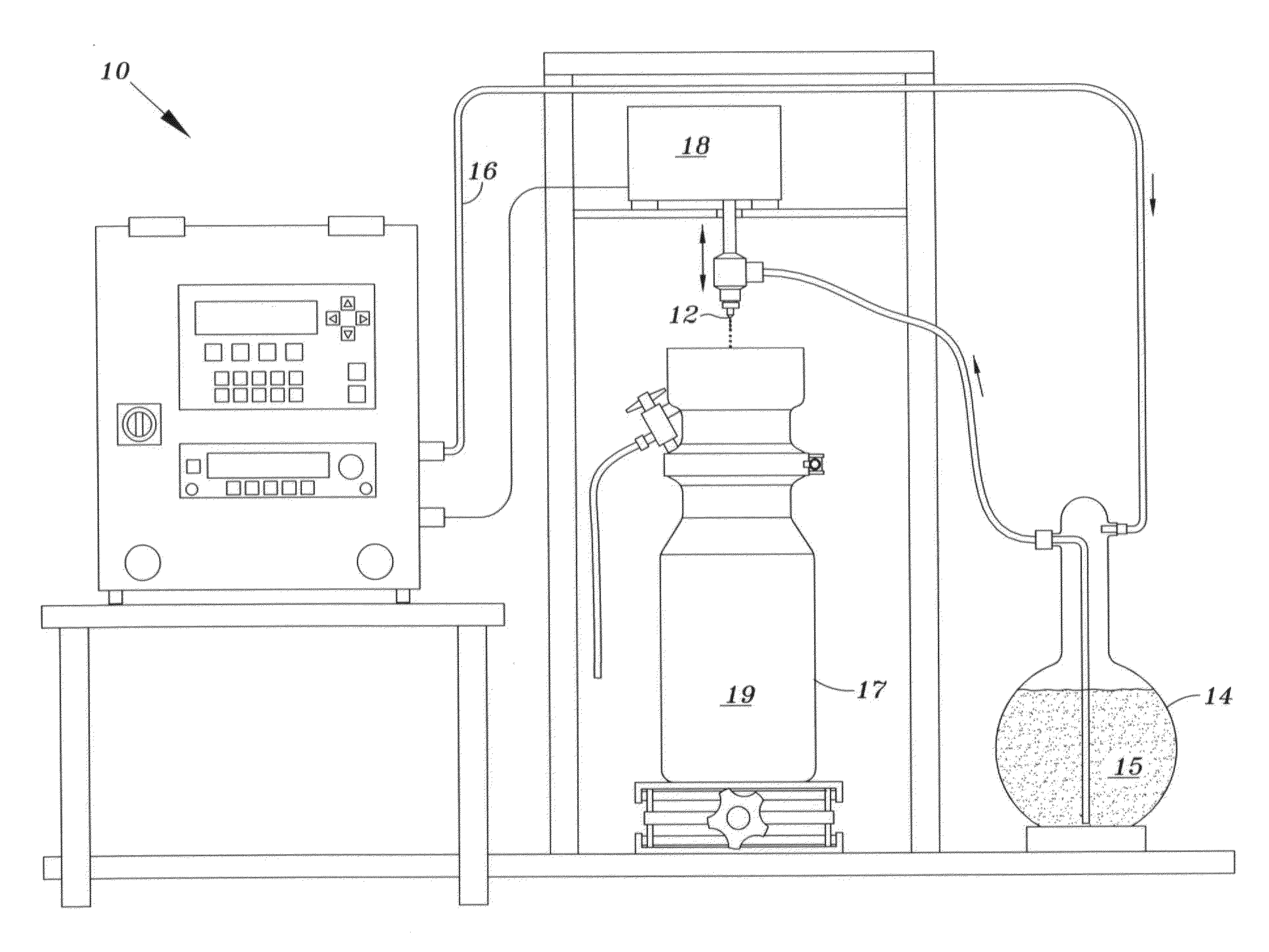
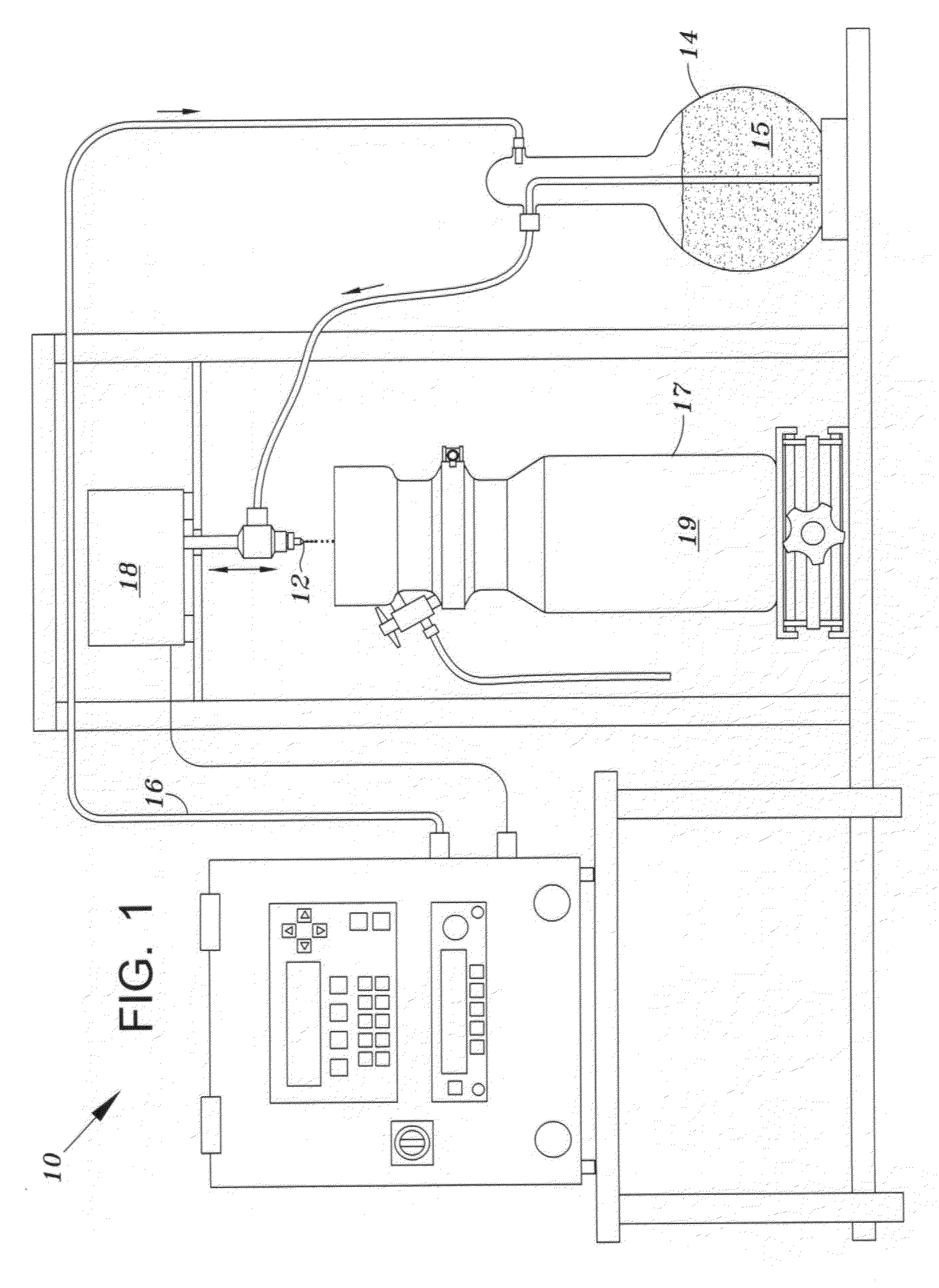
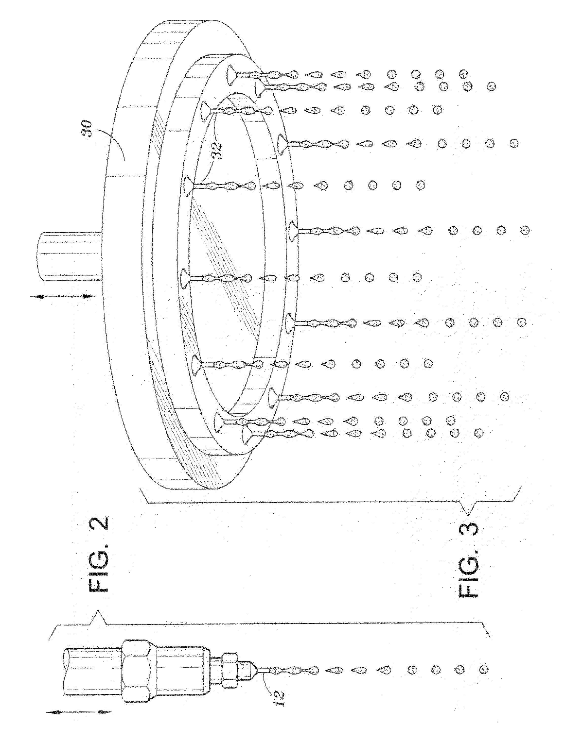
[0021]Referring to FIG. 1, pellet-forming apparatus 10 having a single nozzle is shown to illustrate the principles of the method disclosed herein, which is commonly called “drip casting.” Nozzle 12 receives slurry 15 from feed tank 14, which contains the ceramic raw materials suspended in water. Pressure applied to feed tank 14 by pressure supply system 16 causes slurry to flow through nozzle 12 at a selected rate—preferably in laminar flow. Below nozzle 12 is coagulation vessel 17, which receives the droplets. Vibrator unit 18 is connected to nozzle 12 and is used to supply pressure pulses to the nozzle or directly in the slurry flowing to the nozzle. The resulting vibration of the slurry flow through the nozzle causes the stream exiting the nozzle 12 to break into droplets of uniform size. As droplets fall toward coagulation vessel 17, surface tension effects tend to form the droplets into spheres. Spherical particles are formed without the necessity of a sol-gel reaction, reacti...


PUM

PropertyMeasurementUnit
Temperatureaaaaaaaaaa
Fractionaaaaaaaaaa

Abstract

Proppant material for hydraulic fracturing is provided. The particles of the proppant are formed by drip casting. A slurry of finely divided ceramic particles is flowed through nozzles and formed into droplets under the influence of vibration. Uniform sized, smooth surface, spherical green particles are formed. The green particles are dried and sintered to form the proppant. The proppant is used in the process of hydraulic fracturing of wells.

Description

BACKGROUND OF INVENTION[0001]1. Field of the Invention[0002]This invention relates to hydraulic fracturing of subterranean formations in the earth. More particularly, sintered ceramic proppant particles formed from vibration-induced dripping from a nozzle of a slurry of finely-divided ceramic material are provided, along with a method of use of the particles.[0003]2. Description of Related Art[0004]Hydraulic fracturing is a process of pumping liquids down a well and into a subterranean formation at high rate and pressure, such that a fracture is formed in the rock around the well. After pumping a liquid volume sufficient to widen the fracture adequately, solid particles, called “proppant,” are added to the liquid. After pumping is completed, the well is opened for production of hydrocarbons. The production rate of fluid from the well is usually significantly increased after the fracturing treatment. Vast improvements in the hydraulic fracturing process have been developed since the ...

Claims


Application Information

Patent Timeline
IPC IPC(8): E21B43/267B29B9/00B07B1/00C09K8/80
CPCC09K8/805B29B9/10
Inventor ELDRED, BENJAMIN T.WILSON, BRETT A.GARDINIER, CLAYTON F.DUENCKEL, ROBERT J.
Owner CARBO CERAMICS
Why Eureka
Try Eureka