Differential transmission circuit, optical module, and information processing system

Active Publication Date: 2012-09-13
LUMENTUM JAPAN INC
View PDF13 Cites 24 Cited by
  • Summary
  • Abstract
  • Description
  • Claims
  • Application Information

AI Technical Summary

Benefits of technology

[0037]According to the present invention, it is possible to provide a differential transmission circuit, and an optical module and an information processing system using the same, cap

Problems solved by technology

However, since the transmission line conductors have shapes which are partially meandered, regions for the meandered part are required to be secured, which causes an increase in a pattern area of the transmission line conductors, and thereby it is difficult to perform high density mounting on the printed circuit board.
This is a cause of noise.
In order to suppress the noise, there is a requirement of a countermeasure where a ground conductor layer having no slots is further added on the op

Method used


Image

  • Differential transmission circuit, optical module, and information processing system
  • Differential transmission circuit, optical module, and information processing system
  • Differential transmission circuit, optical module, and information processing system

Examples


first embodiment

[0068]A differential transmission line and an optical transceiver module according to the first embodiment of the present invention will be described. Note that a differential transmission circuit according to the present invention may be defined as an electric circuit provided with a differential transmission line according to the present invention, and that optical modules according to the present invention include optical transceiver modules according to the present invention as example. A differential transmission line is also referred to as a balanced line or differential line.

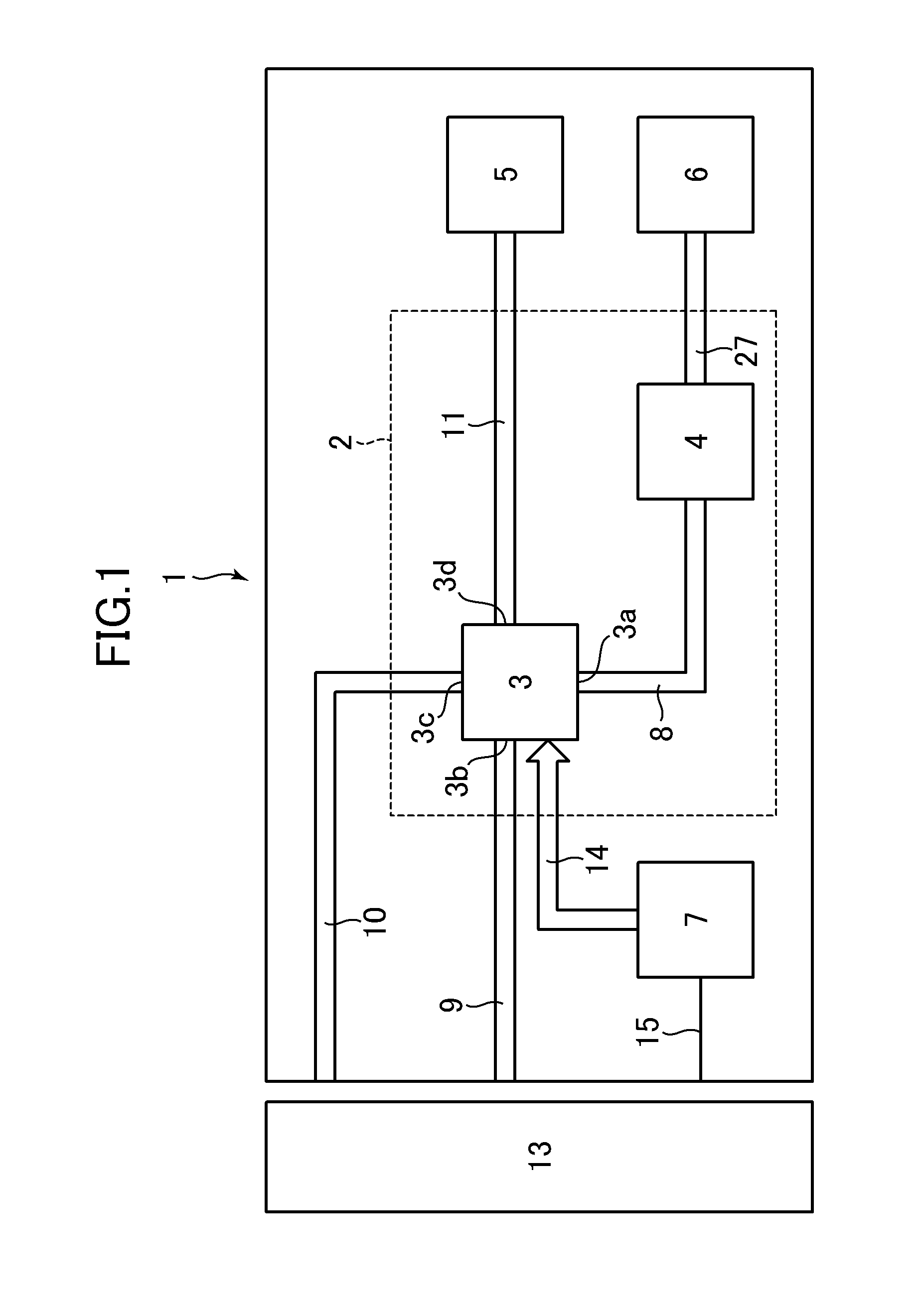
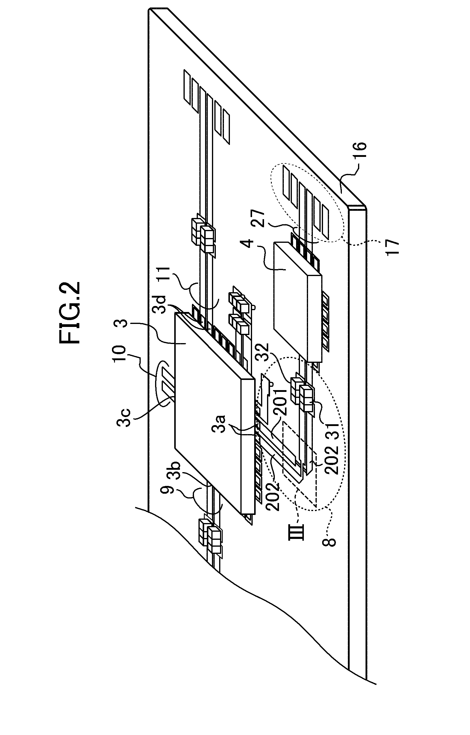
[0069]FIG. 1 is a block diagram of an optical transceiver module 1 according to the first embodiment of the present invention. The optical transceiver module 1 according to the embodiment includes an optical transmission element module 6, an optical reception element module 5, a data transmission unit 2, and a control unit 7. In addition, the optical transceiver module 1 is connected to a transmission dev...

second embodiment

[0117]A basic configuration of the optical transceiver module 1 according to the second embodiment of the present invention is the same as the configuration of the optical transceiver module 1 according to the first embodiment, but shapes of a pair of transmission line conductors of the differential transmission line 8 according to the embodiment are different from those in the first embodiment.

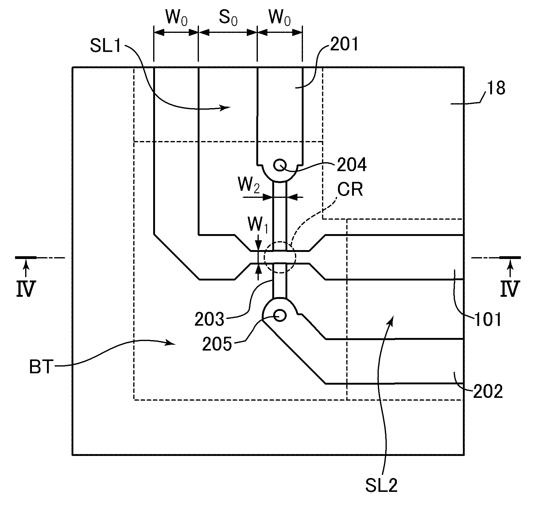
[0118]FIG. 9 is a top view illustrating the vicinity of the bent region of the differential transmission line 8 according to the embodiment. A pair of transmission line conductors are shown in the same manner as the differential transmission line 8 according to the first embodiment shown in FIG. 3. In FIG. 9, the first transmission line conductor is shown by a first upper layer P data conductor film 102, and the second transmission line conductor is shown by a first upper layer N data conductor film 201, a second upper layer N data conductor film 206, a first lower layer N data conductor film...

third embodiment

[0123]A basic configuration of the optical transceiver module 1 according to the third embodiment of the present invention is the same as the configuration of the optical transceiver module 1 according to the second embodiment, but shapes of a pair of transmission line conductors of the differential transmission line 8 according to the embodiment are different from those in the second embodiment.

[0124]FIG. 11 is a top view illustrating the vicinity of the bent region of the differential transmission line 8 according to the embodiment. A pair of transmission line conductors are shown in the same manner as the differential transmission line 8 according to the second embodiment shown in FIG. 9. The second transmission line conductor shown in FIG. 11 has the same configuration as that of the second transmission line conductor shown in FIG. 9. In contrast, in FIG. 11, the first transmission line conductor is shown by a first upper layer P data conductor film 103, a second upper layer P d...


PUM


Abstract

A differential transmission circuit includes a pair of transmission line conductors and a ground conductor layer, wherein the pair of transmission line conductors include a first straight line region where both the pair of transmission line conductors extend in parallel to each other in a first direction with a first width in a first layer, a first cross region where one of the pair of transmission line conductors is formed in the first layer, the other thereof is formed in a second layer, and the pair of transmission line conductors cross the each other in a three-dimensional manner, the first cross region being disposed on the front side of the first straight line region, and wherein each of the widths of the pair of transmission line conductors in the first cross region is smaller than the first width.

Description

CROSS-REFERENCE TO RELATED APPLICATIONS[0001]The present application claims priority from Japanese applications JP 2011-050849 filed on Mar. 8, 2011 and JP 2012-001658 filed on Jan. 6, 2012, the contents of which are hereby incorporated by reference into this application.BACKGROUND OF THE INVENTION[0002]1. Field of the Invention[0003]The present invention relates to a differential transmission circuit, and an optical module and an information processing system using the same, and more particularly to improvement in quality of a transmission signal transmitted on the differential transmission line.[0004]2. Description of the Related Art[0005]A transmission line is used for high-speed digital signal transmission. For example, differential transmission is generally used for digital signal transmission of several hundreds of Mbps or more instead of single-end transmission, and a transmission line for performing the differential transmission is a differential transmission line. The diffe...

Claims


Application Information

Patent Timeline
IPC IPC(8): H05K7/02H01P3/08
CPCH01P1/02H01P3/08H01P3/088H01P3/085H05K1/0245H05K1/111
Inventor KAGAYA, OSAMU
Owner LUMENTUM JAPAN INC
Why Eureka
Try Eureka