Switching controller with valley-lock switching and limited maximum frequency for quasi-resonant power converters

a controller and quasi-resonant technology, applied in the direction of electric variable regulation, process and machine control, instruments, etc., can solve the problems of qr power converter, low efficiency under light-load condition, and potential and achieve the effect of reducing the acoustic noise of transformers and high efficiency of quasi-resonant power converters

Active Publication Date: 2012-09-13
SEMICON COMPONENTS IND LLC
View PDF1 Cites 42 Cited by
  • Summary
  • Abstract
  • Description
  • Claims
  • Application Information

AI Technical Summary

Benefits of technology

[0011]It is therefore an object of the present invention to provide a controller for a quasi-resonant power converter that can limit the maximum switching frequency and achieve valley switching operation under both heavy-load and light-load conditions. Therefore, high efficiency of the quasi-resonant power converter can be achieved over full-range load conditions.
[0012]It is also another object of the present invention to provide a controller for the quasi-resonant power converter with valley-lock function, which is beneficial to reduce the acoustic noise of the transformer during a valley number of the valley switching operation is changing.

Problems solved by technology

However, one drawback of the QR power converter is lower efficiency under light-load condition.
Acoustic noise might be generated during the valley switching operation, which becomes a main issue to be resolved.

Method used


Image

  • Switching controller with valley-lock switching and limited maximum frequency for quasi-resonant power converters
  • Switching controller with valley-lock switching and limited maximum frequency for quasi-resonant power converters
  • Switching controller with valley-lock switching and limited maximum frequency for quasi-resonant power converters

Examples


Embodiment Construction

[0032]The following description is of the best-contemplated mode of carrying out the invention. This description is made for the purpose of illustrating the general principles of the invention and should not be taken in a limiting sense. The scope of the invention is best determined by reference to the appended claims.

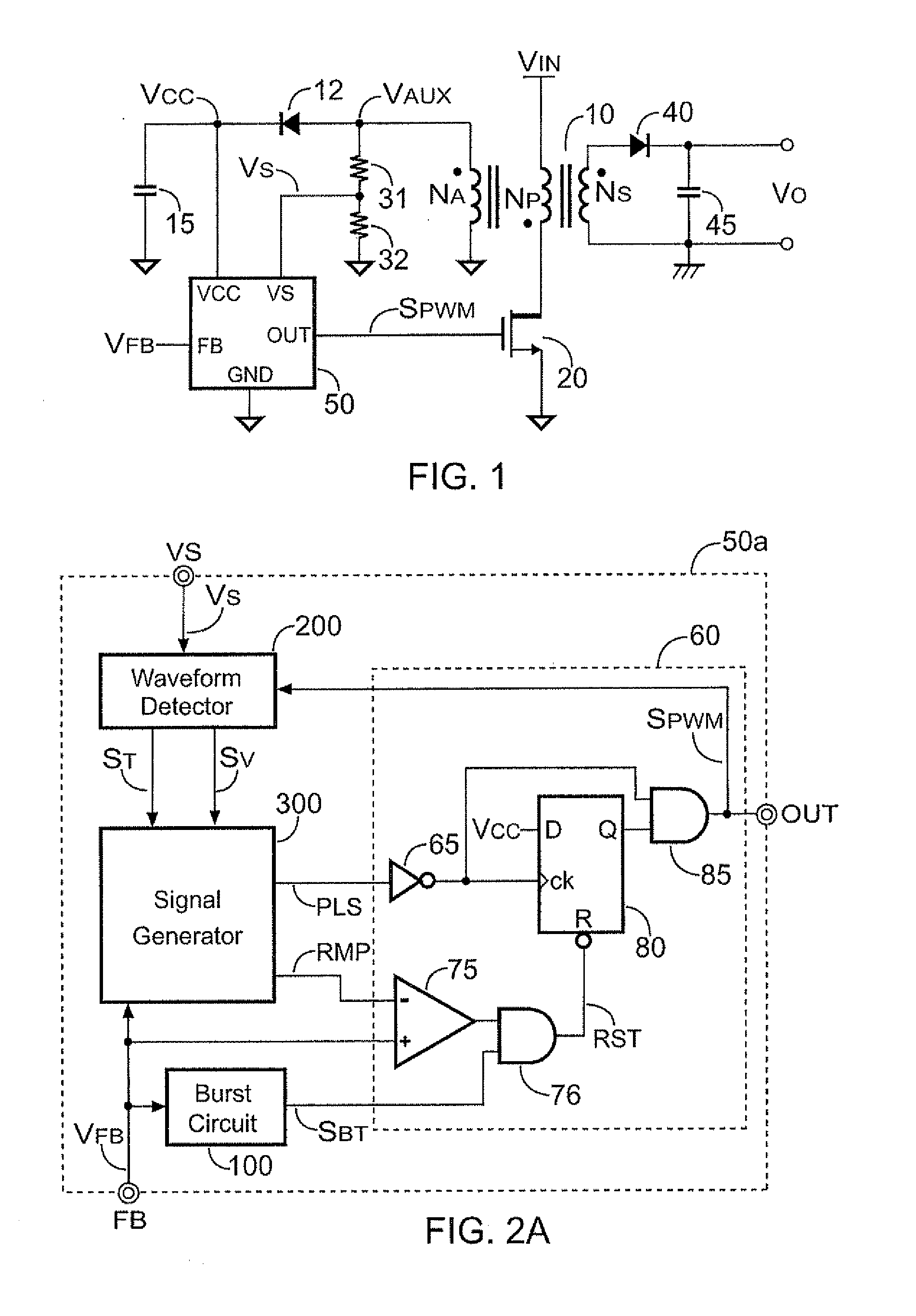
[0033]FIG. 1 shows a quasi-resonant power converter. A transformer 10 has an auxiliary winding NA, a primary winding NP and a secondary winding NS. The primary winding NP is coupled to an input voltage VIN. The secondary winding NS generates an output voltage VO via a rectifier 40 and a capacitor 45. In order to regulate the output voltage VO, a controller 50 generates a switching signal SPWM to switch the transformer 10 via a power transistor 20. A feedback signal VFB is correlated to the output VO of the power converter. The feedback signal VFB is coupled to the controller 50 to generate the switching signal SPWM which is utilized to regulate the output voltage VO of...


PUM


Abstract

The present invention provides a controller for a power converter. The controller comprises a PWM circuit, a detection circuit, a signal generator, an oscillation circuit, a valley-lock circuit, a timing circuit and a burst circuit. The PWM circuit generates a switching signal coupled to switch a transformer of the power converter. A feedback signal is coupled to control and disable the switching signal. The detection circuit is coupled to the transformer via a resistor for generating a valley signal in response to a waveform obtained from the transformer. The signal generator is coupled to receive the feedback signal and the valley signal for generating an enabling signal. The oscillation circuit generates a maximum frequency signal. The maximum frequency signal associates with the enabling signal to generate a turning-on signal. The turning-on signal is coupled to enable the switching signal. A maximum frequency of the turning-on signal is limited.

Description

CROSS REFERENCE TO RELATED APPLICATIONS[0001]This application claims the benefit of U.S. Provisional Application No. 61 / 450,642, filed on Mar. 9, 2011, the contents of which are incorporated herein by reference.BACKGROUND OF THE INVENTION[0002]1. Field of the Invention[0003]The present invention generally relates to power converters; more specifically, the present invention relates to quasi-resonant power converters.[0004]2. Description of the Related Art[0005]To achieve higher efficiency and reduce power loss of a power converter under high switching frequency, quasi-resonant (QR) technique is widely applied. However, one drawback of the QR power converter is lower efficiency under light-load condition. The switching frequency of QR power converter is varied in response to an input voltage and an output load of the QR power converter. Its switching frequency is normally increased when the output load is decreased. Acoustic noise might be generated during the valley switching operat...

Claims


Application Information

Patent Timeline
Patent Type & Authority Applications(United States)
IPC IPC(8): H02M3/335
CPCY02B70/16H02M3/33523Y02B70/1433H02M2001/0035Y02B70/10H02M1/0035
Inventor YANG, TA-YUNGLIN, CHAO-CHIH
Owner SEMICON COMPONENTS IND LLC
Why Eureka
Try Eureka