Turbine or compressor blade

a turbine blade and compressor technology, applied in the field of blades, can solve the problems of disadvantageous comparatively low stability in relation to pressure loading, and achieve the effects of reducing co2 development, reducing energy input, and being resistant and durabl

Inactive Publication Date: 2012-09-13
SIEMENS AG
View PDF7 Cites 17 Cited by
  • Summary
  • Abstract
  • Description
  • Claims
  • Application Information

AI Technical Summary

Benefits of technology

[0011]Since fiber-reinforced plastic is many times more resistant to tensile loads than to pressure loads or shear loads, the blade, and particularly its fastening section in the four of the blade root, is therefore particularly resistant and durable in respect to operating conditions.
[0012]The use of fiber-reinforced plastic, especially CFK, for producing the blade airfoil advantageously opens up the possibility in general of constructing an aerodynamically particularly favorable blade airfoil. This therefore contributes to a reduced energy input, which in turn is advantageously accompanied by a reduced development of CO2. On account of the lower weight of the fiber-reinforced plastic, the blade airfoils of such blades can be even larger than blade airfoils of metal blades, with a blade root of the same size. This also enables an increase of the mass flow.
[0013]The individual holders of the blade root are interconnected by means of at least one flank section for stabilizing the blade root, wherein this flank section is oriented essentially parallel to the carrier.
[0014]Provision is preferably made in this case for two flank sections which are attached in each case on the two lateral edges of each of the holders, with which the respective holder projects over the blade airfoil. Accordingly, the two flank sections lie preferably diametrically opposite with regard to the carrier. In particular, the attachment of the flank sections is again carried out in this case in such a way that these do not come into contact with the laminated fabric web, at least in the region in which the holders project over the blade airfoil. As a result of this, the unwanted pressure stresses in the laminated fabric webs are reliably avoided. In the case of trapezoidal holders, the flank sections are preferably fastened to the two sides of the trapezoid so that the force flux takes place entirely via the flank sections. This reduces the end-side loading of the retaining groove enormously and so evens out the loading in the rotor disk on account of the contact surfaces which are significantly enlarged by the flank sections. Consequently, the steeples which are arranged between two adjacent retaining grooves can be made smaller, as a result of which a compact, space-saving arrangement of retaining grooves in the rotor is possible.
[0015]In an especially preferred embodiment of the invention, each of the holders, in the region of the carrier, projects over the blade airfoil on both sides, at least in the main at right angles to the longitudinal extent thereof. In other words, in such configurations the holders, in the region of the attachment of the blade airfoil, project over the laminated fabric web on both sides so that the laminated fabric, at least in the region there, does not come into contact with the corresponding lateral surfaces of the groove (of the groove flanks). Consequently, the blade, under centrifugal force, bears principally against the groove flanks only via the holders and not via the laminated fabric, so that only the holders experience pressure stresses. This avoids pressure stresses in the root-side laminated fabric regions which could occur on account of centrifugal force action if the root-side laminated fabric were to come into contact with the groove flanks.

Problems solved by technology

CFK, however, disadvantageously has comparatively low stability in relation to pressure loading.

Method used


Image

  • Turbine or compressor blade
  • Turbine or compressor blade
  • Turbine or compressor blade

Examples


Embodiment Construction

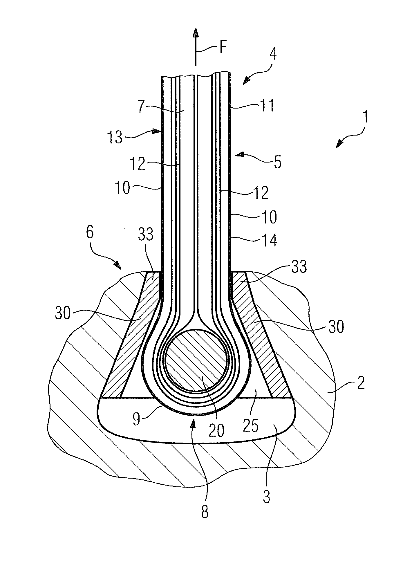
[0035]FIG. 1 shows a turbine rotor assembly 1 in a slightly schematized sectional view. The turbine rotor assembly 1 comprises a rotor 2 consisting of high-grade steel, into which a multiplicity of axial grooves 3 are introduced in a uniform distribution over the circumference. In FIG. 1, only a detail of the rotor 2 in the region of a single axial groove 3 is shown. In the first embodiment which is shown here, each axial groove 3 is essentially constructed as a so-called dovetail groove.

[0036]A turbine blade 4 is accommodated in the axial groove 3. The turbine blade 4 comprises a blade airfoil 5 (only partially shown here), and a blade root 6 which serves for anchoring the turbine blade 4 in the axial groove 3.

[0037]The blade airfoil 5 is produced from a plurality of layered webs 7 consisting predominantly of unidirectional CFK laminated fabric. The webs 7 in this case are folded in such a way—preferably approximately in the middle—that in the region of the fold 8, which results du...


PUM


Abstract

A blade for a turbine or a compressor, at least partially made of fiber-reinforced plastic, in particular carbon fiber reinforced plastic, being particularly durable under operating conditions is provided. The blade includes a blade body and a blade root. The blade body is substantially made of a folded fabric web made of fiber reinforced plastic, wherein a retaining loop is formed in the area of the fold, and wherein a blade surface is formed in the area of the fold, and wherein a blade surface is formed from the overlapping web ends. The blade root includes a longitudinal beam and at least two holders for anchoring the blade in a corresponding groove of a rotor, the holders being preferably each fixedly connected to the beam at both ends. The blade body is suspended on the beam by means of the retaining loop.

Description

CROSS REFERENCE TO RELATED APPLICATIONS[0001]This application is the US National Stage of International Application No. PCT / EP2010 / 067581, filed Nov. 16, 2010 and claims the benefit thereof. The International Application claims the benefits of European Patent Office application No. 09014381.9 EP filed Nov. 17, 2009. All of the applications are incorporated by reference herein in their entirety.FIELD OF INVENTION[0002]The invention relates to a blade of a turbine or of a compressor.BACKGROUND OF INVENTION[0003]A blade of a turbomachine on the one hand normally comprises an aerodynamically curved blade airfoil and, on the other hand, normally comprises a blade root which serves for anchoring the blade in a corresponding groove of a rotor. The rotor equipped with blades is referred to as rotor assembly in the following text.[0004]As a comparatively new type of material for producing blades, even carbon-fiber reinforced plastic (CFK) is currently taken into consideration. The production...

Claims


Application Information

Patent Timeline
Patent Type & Authority Applications(United States)
IPC IPC(8): F01D5/14
CPCF01D5/282F01D5/3007F05D2300/603F05D2230/90F05D2260/36
Inventor BENKLER, FRANCOISLINK, MARCOMATTHIAS, TORSTENMITTELBACH, MARCMORTHORST, MARIONROLLMANN, MICHAELSAATHOFF, HORSTWIGGER, HUBERTUS MICHAEL
Owner SIEMENS AG
Why Eureka
Try Eureka